and
and 
-
-
-
-
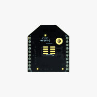
 Plugins
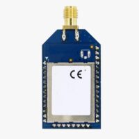
Radio module Long Range (LR)
101,00€ This product has multiple variants. The options may be chosen on the product page -
 Plugins
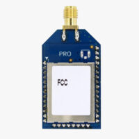
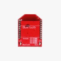
Radio module eXtra Long Range (XLR)
161,00€ This product has multiple variants. The options may be chosen on the product page -
-
-
Sale!
 Made in Europe
 -
Sale!
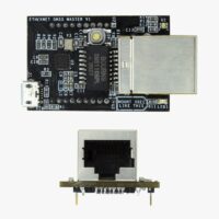
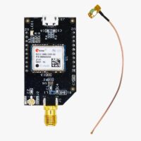
 Plugins
4G NTRIP Master
156,00€ This product has multiple variants. The options may be chosen on the product page -

-
Sale!
-
-
Sale!
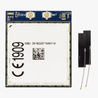
 Made in EuropePlugins
PointPerfect L-Band Corrections Receiver NEO-D9S
Original price was: 125,00€.99,00€Current price is: 99,00€. -