Update (19/09/2026): We have plenty of stock of all our products, find us also in and    How to get a quotation

User Guide: simpleGNSS Pro

Product overview

You can use simpleGNSS Pro as a standalone board or as an Arduino shield.

The main component of simpleGNSS Pro is u-blox NEO-F10N.

Get started

Step A
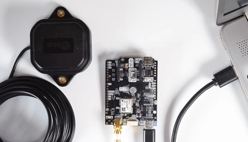
Connect antenna
Step B
Connect to PC and u-center 2
Step C
Configure receiver
  1. Connect the GNSS antenna to your receiver. The simpleGNSS board supports L1 and L5 bands. For best performance, we recommend using a dual-band L1/L5 antenna (like u-blox ANN-MB1-00 Dualband (L1/L5) GNSS Antenna) or a triple-band L1/L2/L5 antenna (like Budget Survey Tripleband GNSS Antenna). An L1/L2 antenna can also be used, but it will not allow you to take full advantage of the receiver’s L1/L5 capabilities.
  1. Place GNSS antenna outdoors in a place with a good view of the sky for testing functionality. Otherwise, you won’t see the satellite view and signal.
  1. Download u-center 2 for Windows 10/11 (64-bit). Important: Select the build for u-blox M10/F10/X20 products, not the older release for M8/M9/F9 or legacy GNSS receivers.
    After installation completes, enter your u-blox Support Portal credentials and log in via your browser. If you don’t have an account, click Register.
  2. An internet connection is required for the first login, but once u-center 2 has started, it can be used offline in subsequent sessions.
  3. Open u-center2. Select the COM port to connect your receiver. If you don’t know which COM port your receiver is connected, check the Device Manager of your PC.
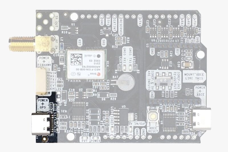
  4. Connect the receiver to your PC via the USB port labelled as POWER+GPS using USB cable.
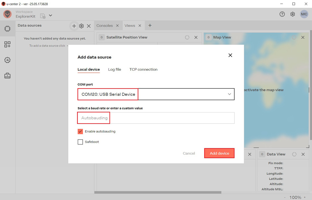
  1. Click Devices on the left menu bar, then click the + icon. Select the device’s COM port and choose Autobauding for automatic baud rate detection. Finally, click Add device.
  1. With current FW301, there is an internal UBX messages enabled that disturbs the NMEA stream, and also GPS L5 is disabled by default. To get the best out of the receiver we recommend changing this. We have prepared configuration file simpleGNSS_FW600_1Hz_debug_message_off-GPSL5_on-01.txt to disable this internal message and enable GPS L5 for maximum performance. Save it on your PC.
  2. In the menu bar, click the gear icon to open Device Configuration. Under Saved Configurations, click +Import, choose your configuration file, and click Open to import it.
  3. Click Send. A green check mark will appear under Configuration changes to confirm the action.

Hardware

You can use simpleGNSS Pro as a standalone board or as an Arduino shield.

The main component of simpleGNSS Pro is u-blox NEO-F10.

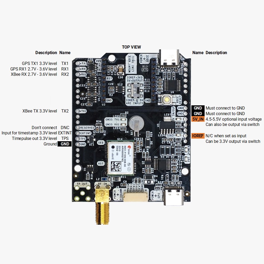
Pinout

Power

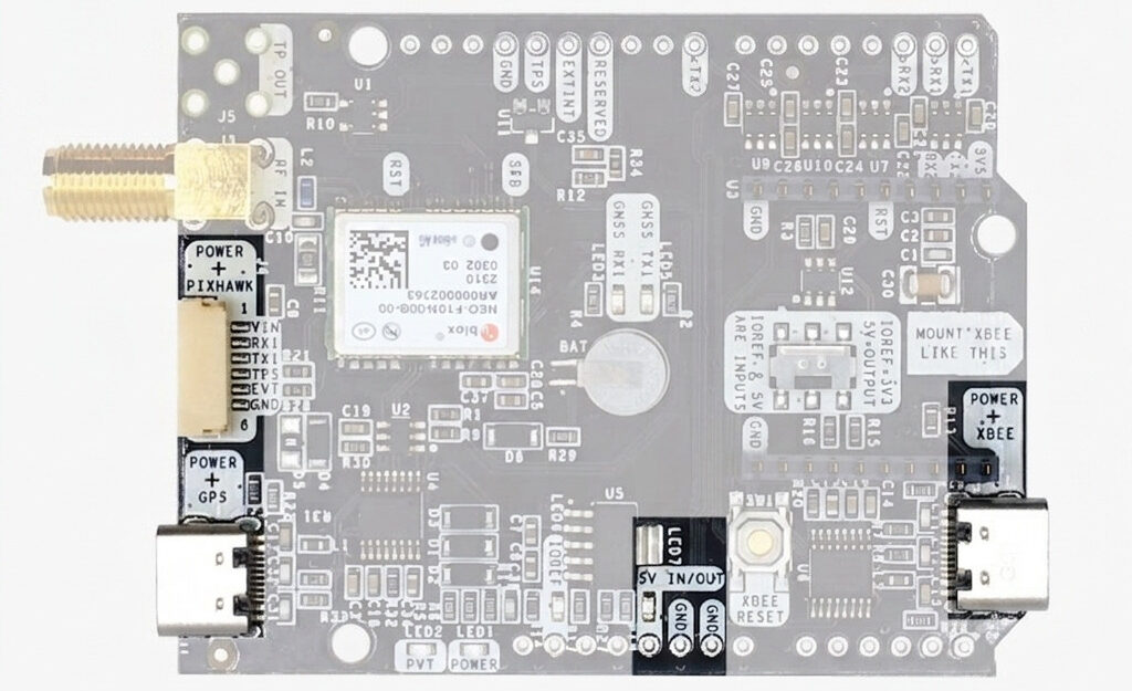
The simpleGNSS board can be powered from 4 different sources:

  • GPS USB port.
  • XBEE USB port.
  • Pixhawk connector.
  • Arduino rail.

Only 1 of them is needed to use the board, but you can also connect the 4 at the same time, there’s no risk.

This board has a High Power (HP) XBee socket. If you connect a device that requires high power to the XBee socket, you will have to make sure your power supply can provide this power.

  • Use only high quality USB-C cables, not longer than 1 meter.
  • If you connect the board through a USB hub to your PC/Tablet or your PC has low power USB ports, you will have to connect the second USB port directly to a wall plug or high power USB port.

Antenna

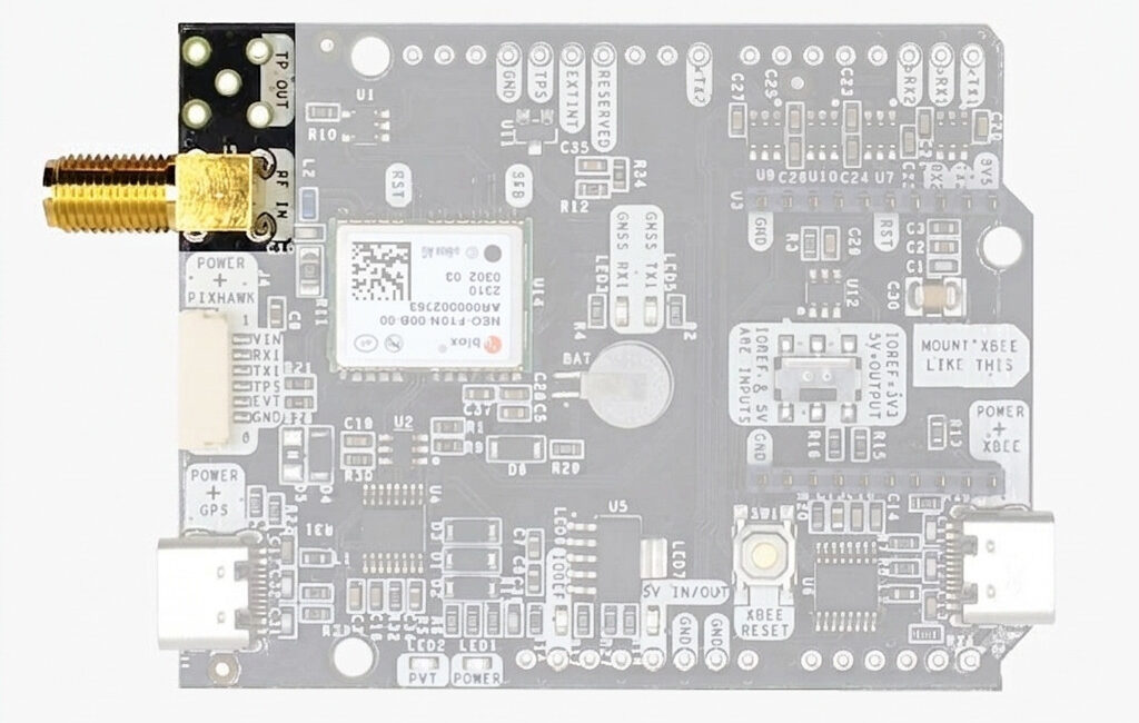
simpleGNSS Pro requires a good quality GPS/GNSS dual band L1/L5 antenna, that you can connect to the SMA labelled “RF IN”. The board is compatible with both active antennas supporting 3.3V supply and passive antennas. The maximum output current is 75mA @ 3.3V. If you use it with the traditional cheap GPS antennas widely available, you will not achieve the expected performance. That being said, just connect the antenna to the SMA connector without using tools (the strength of your fingers is enough). It is recommended to connect the antenna before powering the board. The installation of the antenna is also a key point to achieve the best results. The GPS/GNSS antenna should always be installed with the maximum possible view of the sky. In addition, if possible, it should be installed with a metallic plane behind, e.g. rooftop of the car, on a metal plate bigger than 20cm, etc. If you want to learn how installation impacts performance, please have a look at our GPS/GNSS antenna installation guide.

Interfaces

simpleGNSS Pro board has a few interfaces that we will now explain in detail.

USB GPS

This USB-C connector gives you access to UART1 of NEO-F10 module via an FTDI USB-to-UART converter. u-blox F10 doesn’t have native USB interface. If your PC doesn’t recognize the device automatically, you might need to install the VCP driver from FTDI: https://ftdichip.com/drivers/vcp-drivers/.

You can receive NMEA with the position, or have full access to the NEO-F10 using the u-center tool: https://www.u-blox.com/en/product/u-center.

You can connect this interface to your preferred mobile phone, tablet, or PC and start receiving NMEA data.

You can also connect this USB to your mobile phone using our OTG cable.

USB XBee
manual simpleGNSS Pro usb xbee

This USB-C connector gives you access to the UART of the XBEE radio (if you mount one), via an FTDI USB-to-UART converter. If your PC doesn’t recognize it automatically, you will need the VCP driver from FTDI: https://ftdichip.com/drivers/vcp-drivers/.

To use this connector only as a power source, you don’t need any driver. You can use your PC, or connect to your usb wall adapter.

To use this connector to configure an XBee radio, you will have first to disable data output on NEO-F10T, as this USB interface shares connection to the XBee device with the NEO-F10 module.

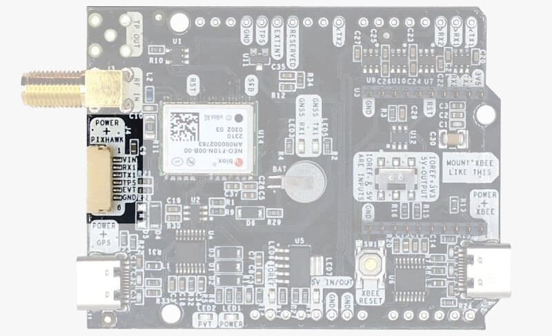
Pixhawk Connector

This connector is a standard JST GH that can be used to connect the simpleGNSS Pro to a Pixhawk autopilot.
You can also use this connector to power the board.

The Pixhawk JST-GH connector is following the Pixhawk standard:

  • 1: 5V_IN.
  • 2: NEO-F10 UART1 RX (3.3V level).
  • 3: NEO-F10 UART1 TX (3.3V level).
  • 4: NEO-F10 timepulse output (3.3V level).
  • 5: NEO-F10 EXTINT time synchronization input, maximum voltage 3.6V.
    This input is filtered to avoid glitches.
  • 6: GND.

In case you want to build your own cable to connect to this connector, the mating aerial connector is JST GHR-06V.

Note that the board only includes GPS and doesn’t include magnetometer.

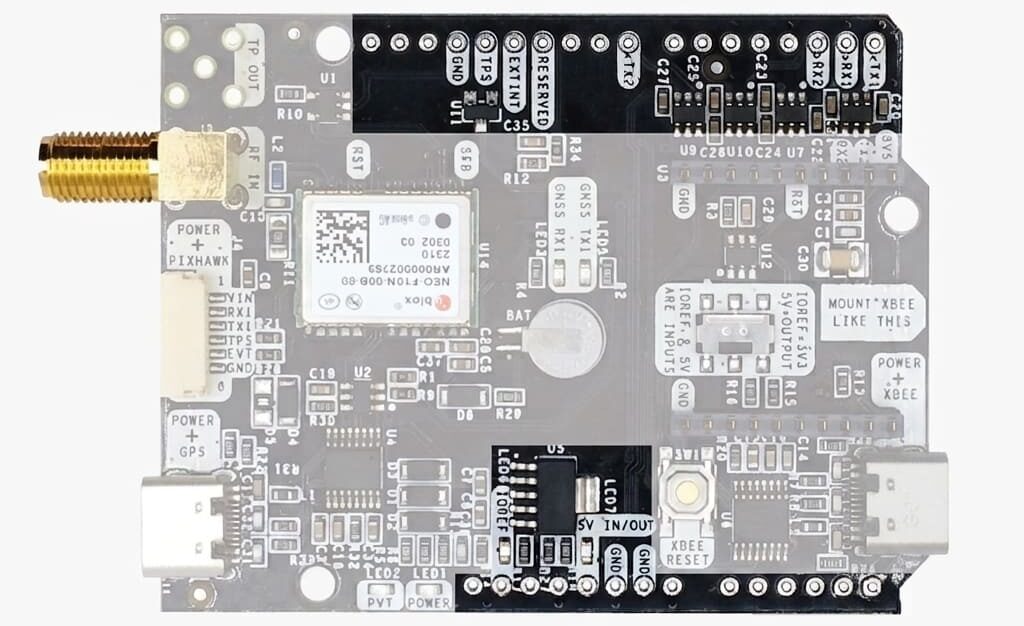
Arduino Rails

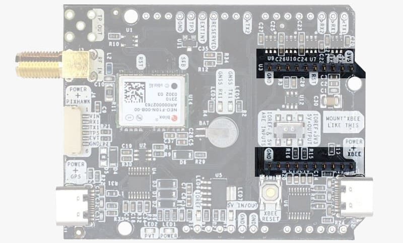
simpleGNSS has optional rails to connect to other Arduino UNO compatible devices.

  • GND: ground is available in the standard arduino pins. You should always connect this line to your other board.
  • 5V IN/OUT:
    • When the LED next to this pin is OFF, can power simpleGNSS Pro from this pin.
      For example, just plug it on top of an Arduino UNO board, and simpleGNSS Pro will turn ON.
    • Alternatively, you can now use simpleGNSS Pro to power shield board.
      Just turn ON the switch “5V=OUTPUT” and simpleGNSS Pro board will output 5V at this pin.
  • IOREF. This pins affect the functionality of TX1,RX1,TX2,RX2,SDA and SCL pins.
    • When plugging simpleGNSS Pro board on top of Arduino UNO or Raspberry Pi, this pin is used to automatically defined the voltage level of the communication pins (TX1,RX1,TX2,RX2,SDA,SCL).
    • When wiring your own cables to board,  this is an input that will define the voltage levels of the pins.
      If you input 1.8V, the next pins will be 1.8V level. It supports from 1.2V to 5.5V.
    • If you want to connect wires to the listed pins and 3.3V is OK for you, you just need to enable the switch “IOREF=3.3V”
  • TX1,RX1,TX2,RX2,SDA,SCL: These pins work with the voltage level defined by IOREF.
    • TX1: NEO-F10 UART1 TX.
    • RX1: NEO-F10 UART1 RX.
    • TX2: XBee UART TX (this pin is also connected to NEO-F10 UART1 RX).
    • RX2: XBee UART RX (this pin is also connected to NEO-F10 UART1 TX).
High Power (HP) XBee socket
You can use this socket to connect an XBee compatible radio. The following pins are available:
  • VCC, which is a 3.3V output with maximum current 1A constant and peak 1.5A.
  • XBee UART RX, at 3.3V level.
  • XBee UART TX, at 3.3V level.
  • GND.
This interface is connected to NEO-F10 UART1.
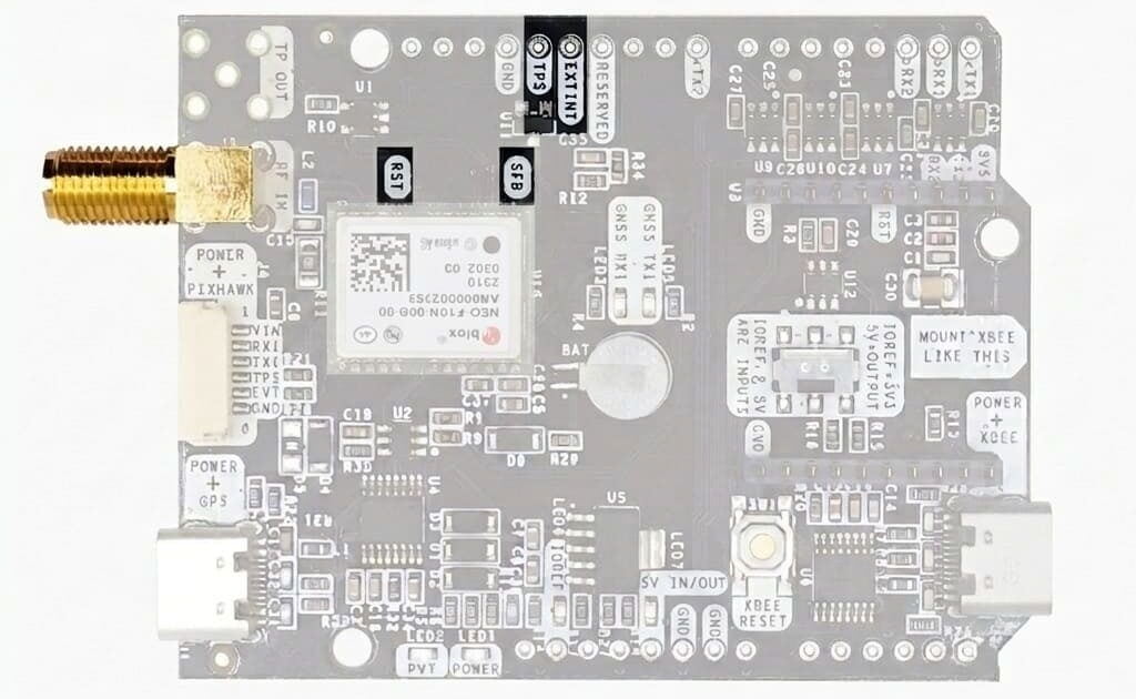
Special function pins

In addition to above, there’s also a few additional pins available for the most advanced users.
If you are going to use simpleGNSS Pro connected on top of an Arduino or Raspberry Pi and you don’t use any of these pins, it’s recommended to not connect the pins: you can cut the header in this pins to avoid the connection, and prevent unexpected behaviors.

  • Timepulse (TPS): 3.3V configuration time pulse output. This pin is connected directly to NEO-F10T and has limited drive output (4 mA drive/sink current). For a timepulse with high output drive (25mA drive/sink current and high speed rise/fall time) you can use the second onboard SMA labelled “TP OUT”.
  • Extint (EXTINT): time synchronization input, maximum voltage 3.6V. This input is filtered to avoid glitches.
  • Safeboot (SF)
  • Reset_N (RST)
LEDs

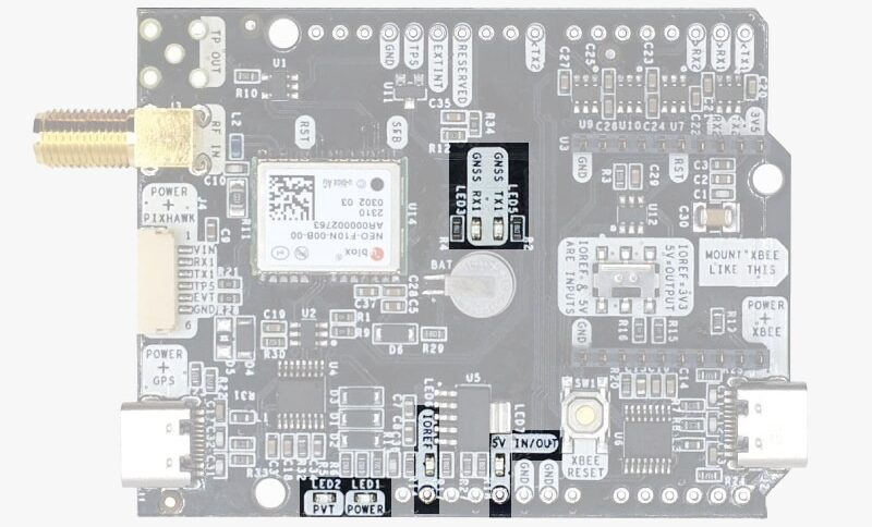
The board includes 7 status LEDs, which indicate that:

  • POWER: the simpleGNSS Pro board has power.
  • PVT: u-blox default configuration for TIMEPULSE pin is used: OFF when no fix, 1-pulse-per-second when valid position. This LED has special color GREEN.
  • XBEE>GPS: The XBEE radio is receiving data over the air and sending it to the NEO-F10.
  • GPS>XBEE: The NEO-F10 is outputting data that the XBEE radio is receiving and sending over the air.
  • 5V IN/OUT: Will indicate you if there is voltage on that pin.
  • IOREF: Will indicate you if the IOREF pin is enabled.
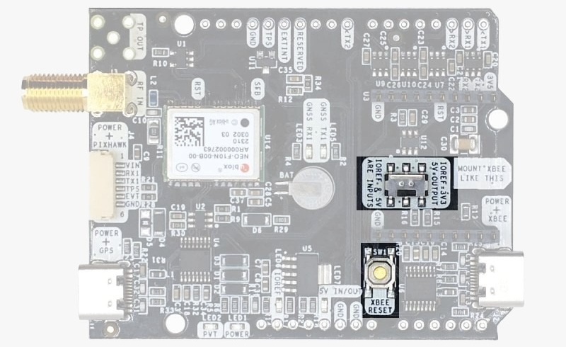
Buttons and switches

There’s only one button: XBee Reset, and the good news is that you probably will not have to use it. This button is used to program the XBee radio if you want to update firmware, etc.

There’s only one switch: the switch under the XBee socket lets you choose which UART you want to connect to the XBee socket.

Accessories

You can add any of these features (and more) with our XBee plugins:

How to add plugin

  1. To connect the communication plugin to the XBee socket, simply insert it into the XBee connector on the board. If you used our configuration file, no extra changed needed to add plugin to your board.
hookup guide simpleRTK4-Optimum addplugin

Got any questions or requests?
Contact us! We'll answer <24 hours!

Contact ArduSimple
Close

Access your Account and orders

Or

New customer? Create your account
ArduSimple – high precision RTK survey equipment and solutions made simple

Want to learn more about GPS and RTK?

If you are busy right now, our engineers can send you 3 short e-mails, explaining all you need to know to start your project.