 and
and 

User Guide: simpleRTK 4 Dual
Overview
You can use simpleRTK 4 Dual as a independent GNSS receiver by connecting it to your PC or tablet. Additionally, it can be used as an add-on board for your projects, such as an Arduino shield. The main component of simpleRTK 4 Dual is the u-blox ZED-X20D all-band (L1/L2/L5/L6 + L-band) RTK GNSS module.
Get started
Step A: Connect the antenna
- Connect the GNSS antenna(s) to your receiver.
- Place the GNSS antenna(s) outdoors with a good view of the sky for testing functionality. Otherwise, you won’t have any satellites in view nor receive signal data.
Step B: Connect to u-center 2
You can download u-center 2 here.
It has been tested on Windows 10 and Windows 11 (64 bit) platform. Once the installation has completed successfully, you need to enter your u-blox support portal account credentials and log in with a browser. If you don’t have a u-blox account click Register. Follow this quick quide to connect.
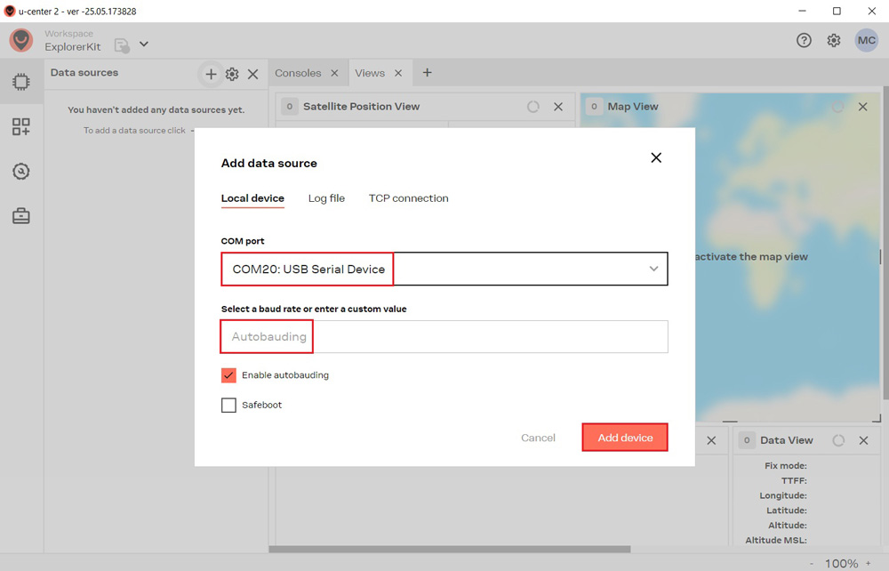
- Connect the receiver to your PC via the USB port labelled as POWER+GPS.
- Click the Devices icon on the left menu bar, click + icon. Select the COM port of the device. Select Autobauding for automatic detection of the baud rate. Click Add device.
Step C: Get RTK corrections
To achieve centimeter- or millimeter-level accuracy with our GNSS receivers, RTK corrections are required. NTRIP (Networked Transport of RTCM via Internet Protocol) is a protocol used for streaming GNSS data over the internet. It facilitates the transmission of real-time correction data from a reference station to a rover or user device.
If you don’t have your own base station for corrections, you can find third party NTRIP corrections at RTK Correction Services in your Country to gain credential (server address, port, user and password) of NTRIP. You can connect to NTRIP using a PC, smartphone, or our Communication Plugins.
Before starting, make sure your receiver is configured as a Rover. Follow this hookup guide to receive corrections on your PC.
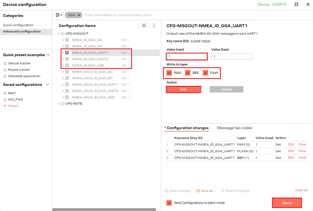
- To connect to the caster for correction data, UBX-NAV-PVT or NMEA standard GGA messages must be enabled. You can skip this step if you load our Rover configuration file.
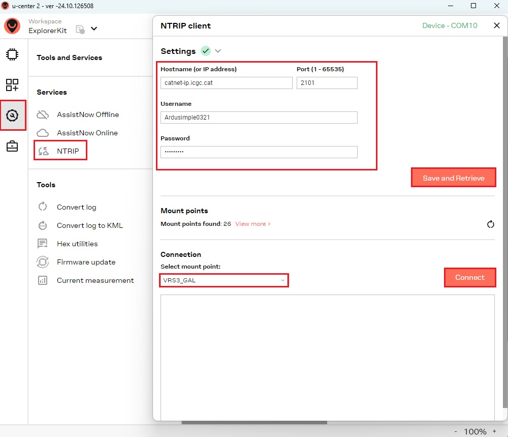
- Go to Tools and Service –> Services –> NTRIP. Enter the hostname or IP address, port, username and password of the NTRIP caster.Click Save and Retrieve to get an up-to-date list of all available mount points.Select mount point then click Connect.
If you are an advanced user seeking detailed information, please refer to the integration guide at u-blox ZED-X20 configuration page.
Step D: Heading configuration
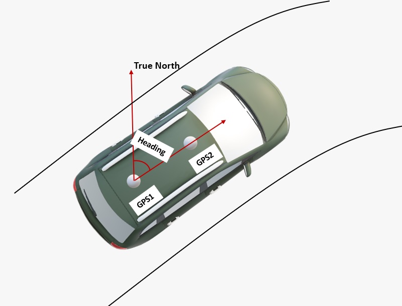
- The heading result is the clockwise angle from True North to the baseline that runs from the master antenna (labeled GPS1 on the board) to the slave antenna (labeled GPS2). The pitch angle refers to the angle of the vehicle or drone relative to the horizontal plane.
- By default, the antennas should be installed longitudinally along the vehicle, with the master antenna (GPS1) positioned at the rear.
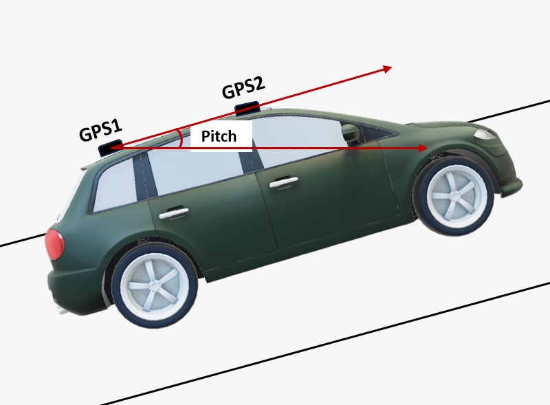
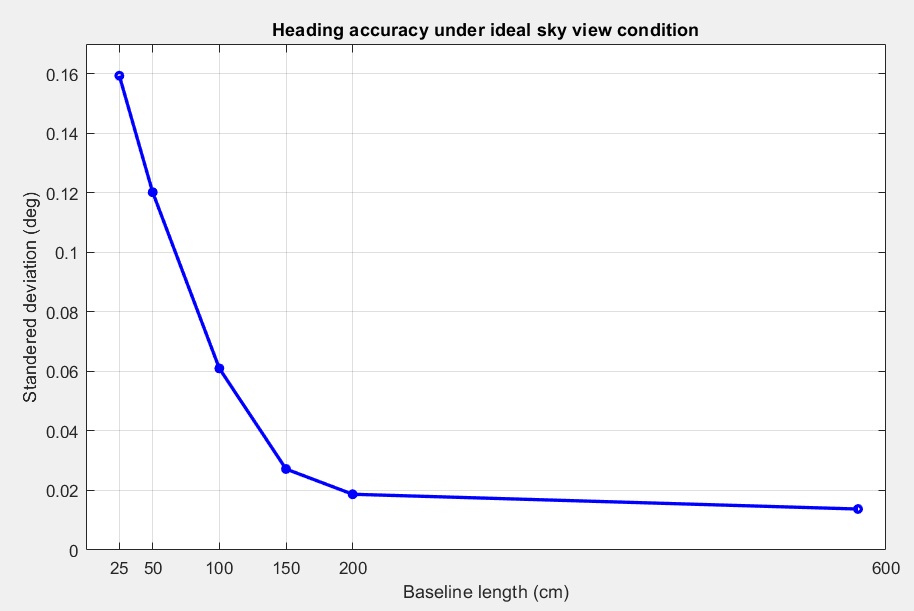
- A minimum distance is required between the two antennas for accurate heading calculations. Heading accuracy improves with a longer baseline (the distance between the antennas). A baseline of at least 1 meter is generally required to achieve satisfactory sub-degree precision under non‑ideal conditions. However, for many vehicles, this is not practical. With a high‑quality installation and a 0.5‑meter baseline, you can achieve decent results. At 0.3 meters, it is possible to obtain a heading, but the output may be somewhat noisy.
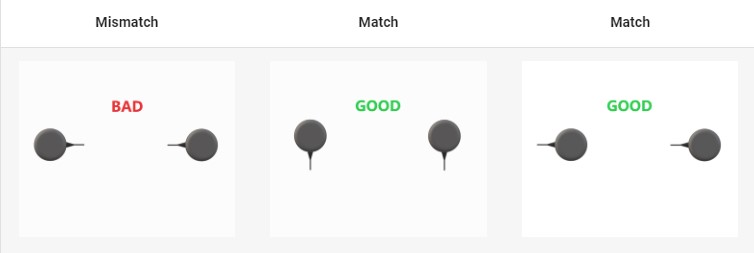
- For best performance, both GNSS antennas should be identical and oriented in the same direction relative to each other. For example, the antenna cables should exit from the same side on both units. This ensures the best alignment of the RF phase centers, which is critical for heading accuracy (note that the actual RF phase center is often offset from the antenna’s physical center). Additionally, the RF cable lengths for both antennas must be identical to achieve optimal results.
Hardware
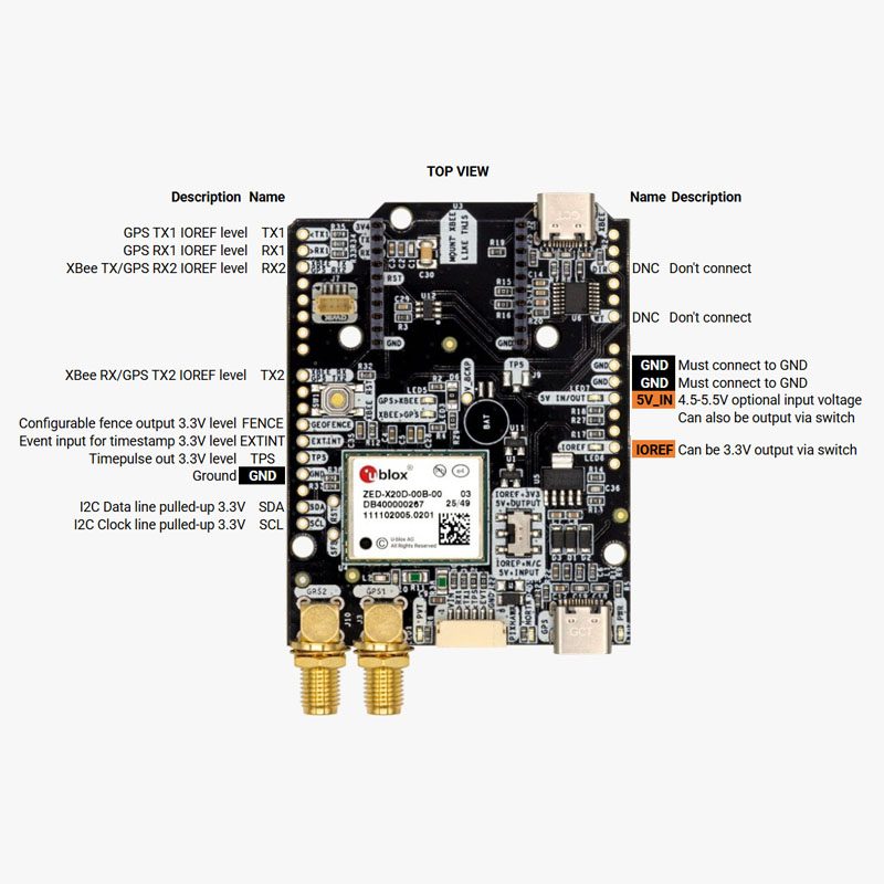
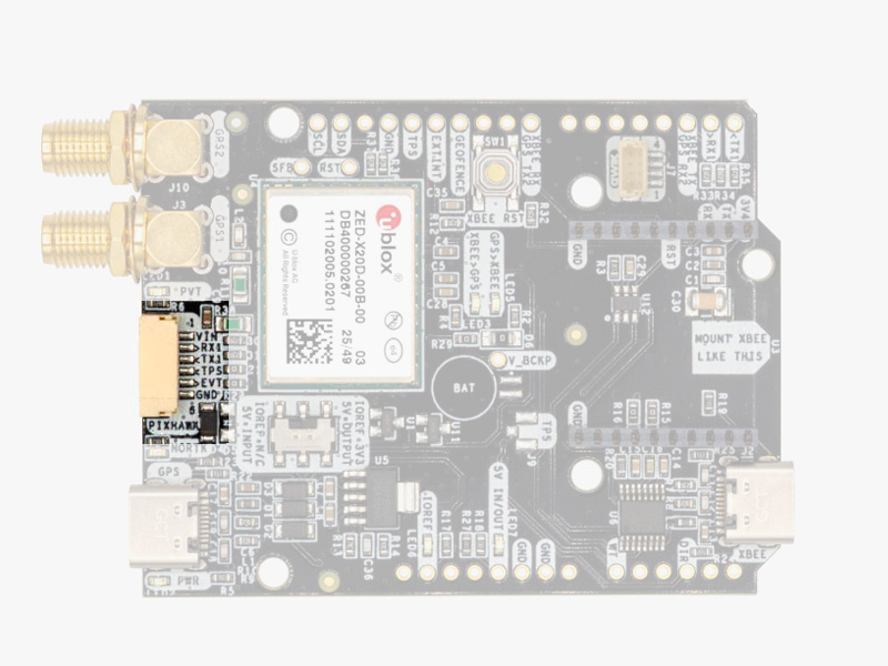
Pinout
Power
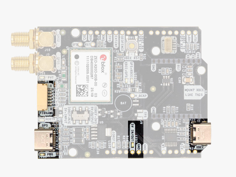
The simpleRTK 4 Dual can be powered from 4 different sources:
- GPS USB port
- XBEE USB port
- Pixhawk connector
- Arduino rail
Only one of them is needed to power the board, but you may connect more than one without any risk.
The simpleRTK 4 Dual has a High Power (HP) XBee socket. You can connect any XBee accessory to it. If you connect a device that requires high power to the XBee socket, you will have to make sure your power supply can provide this power.
- Use only high quality USB-C cables, not longer than 1 meter.
- If you connect simpleRTK 4 Dual through a USB hub to your PC/Tablet or your PC has low power USB ports, you will have to connect the second USB port directly to a wall plug or high power USB port.
GPS/GNSS Antennas
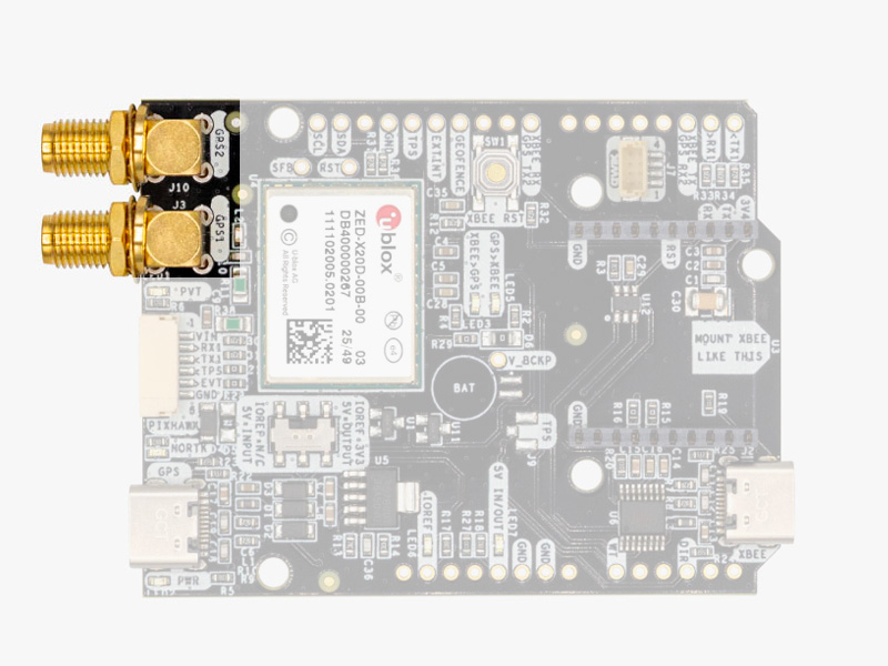
The simpleRTK 4 Dual does not include, but requires a good quality GPS/GNSS antenna. It supports all bands L1/L2/L5/L6 and L-band. If you want to get the most out of this module, we recommend the u-blox ANN-MB2 Tripleband GNSS Antenna. The board supports both active antennas (with 3.3V supply) and passive antennas. The maximum output current is 150mA @ 3.3V. If you use it with the traditional cheap GPS antennas widely available, you will not achieve the expected performance.
IMPORTANT: It is mandatory to connect the antenna before powering the board. The installation of the antenna is also a key point to achieve the best results. The GPS/GNSS antenna should always be installed with the maximum possible view of the sky. In addition, if possible, it should be installed with a metallic plane behind, e.g. rooftop of the car, on a metal plate bigger than 20cm, etc.
If you want to learn how installation impacts performance, please have a look at our GPS/GNSS antenna installation guide or watch this video.
Interfaces
simpleRTK 4 Dual board has a few interfaces that we will now explain in detail.
USB GPS
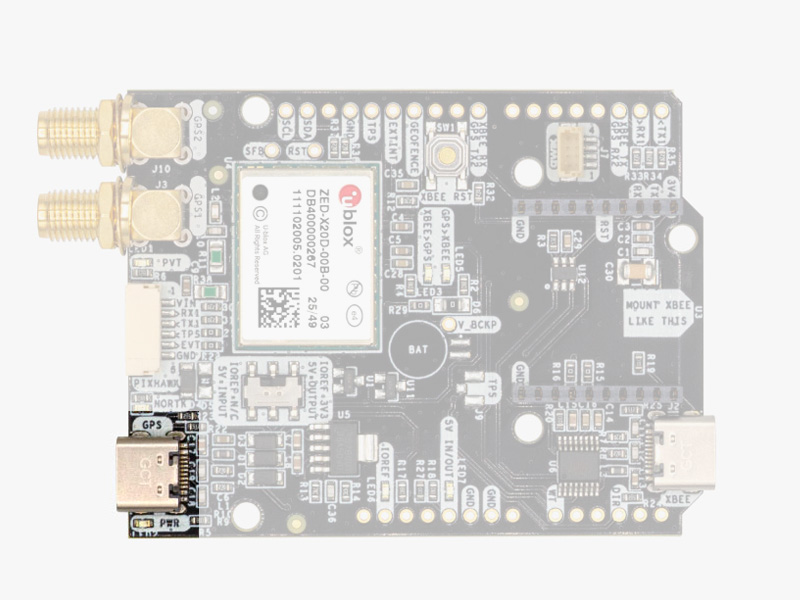
This USB-C connector gives you access to the native USB from the ZED-X20D module. You can receive NMEA with the position, or have full access to the ZED-X20D specifications using the u-center 2 software. You can also connect this USB to your mobile phone using our OTG cable.
If you use Windows 10, no drivers need to be downloaded so ignore the next paragraph. If you experience problems with the above drivers in Windows 7/8 devices, try with the alternative driver that you can download from this link: https://www.ardusimple.com/wp-content/uploads/2020/06/zed-ubloxusb.zip
USB XBee
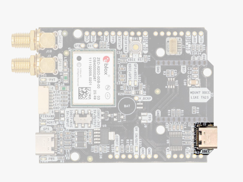
This USB-C connector gives you access to the UART of the XBEE radio (if you mount one), via an FTDI USB-to-UART converter. We find very practical to use this connector to power the board, so you can then connect and disconnect the GPS USB as your wish, without removing the power to the board. To use this connector only as a power source, you don’t need any driver. You can use your PC, or connect to your USB wall adapter.
To use this connector to configure an XBee radio, you will need the VCP driver from FTDI: https://ftdichip.com/drivers/vcp-drivers/
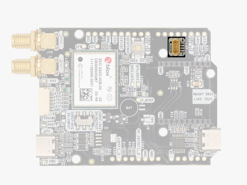
Pixhawk connector
This connector is a standard JST GH that can be used to connect the simpleRTK4 Optimum to a Pixhawk autopilot. You can also use this connector to power the board. The Pixhawk JST-GH connector is following the Pixhawk standard:
- 1: 5V_IN
- 2: ZED-X20P UART1 RX (3.3V level)
- 3: ZED-X20P UART1 TX (3.3V level)
- 4: Timepulse output (3.3V level)
- 5: Event input (3.3V level)
- 6: GND
In case you want to build your own cable to connect to this connector, the mating aerial connector is JST GHR-06V. Please note that the board only includes GPS and doesn’t include magnetometer.
Arduino rails
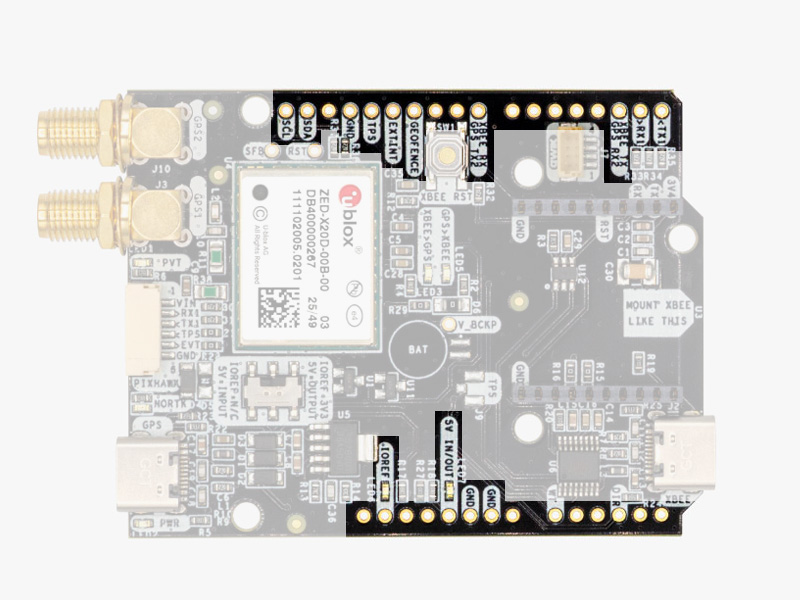
The simpleRTK 4 Dual has optional rails to connect to other arduino UNO compatible devices.
- GND: ground is available in the standard arduino pins. You should always connect this line to your other board.
- 5V IN/OUT:
- When the LED next to this pin is OFF, can power simpleRTK4 Optimum from this pin.
For example, just mount it on top of an Arduino UNO board, and simpleRTK4 Optimum will turn ON. (check if your arduino can power 300mA @ 5V shields). - Alternatively, you can now use simpleRTK4 Optimum to power other shields.
Just turn ON the switch “5V=OUTPUT” and simpleRTK4 Optimum board will output 5V at this pin.
- When the LED next to this pin is OFF, can power simpleRTK4 Optimum from this pin.
- IOREF: TX1, RX1, TX2, and RX2 always operate at 3.3V logic levels.
- TX1,RX1,TX2,RX2,SDA,SCL: These pins always operate at 3.3V logic levels.
- TX1: ZED-X20P UART1 TX
- RX1: ZED-X20P UART1 RX
- TX2: ZED-X20P UART2 TX (this pin is also connected to Xbee UART RX).
- RX2: ZED-X20P UART2 RX (this pin is also connected to Xbee UART TX).
- SDA: ZED-X20P i2C SDA
- SCL: ZED-X20P I2C SCL
High Power (HP) XBee socket
The simpleRTK 4 Dual has a High Power (HP) XBee socket. You can use this socket to connect an XBee compatible radio. The following pins are available:
- VCC, which is a 3.3V output with maximum current 1A constant and peak 1.5A.
- XBee UART RX, at 3.3V level
- XBee UART TX, at 3.3V level
- GND
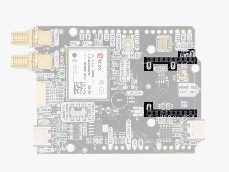
Qwiic connectors
If you already own a Sparkfun Qwiic accesory, you can use it with the simpleRTK 4 Dual. However, due to high power requirements in some configurations, the board cannot be powered from the Qwiic connector directly. When connecting Qwiic accesories:
- Power simpleRTK 4 Dual from one of the 4 power sources: USB GPS, USB XBEE, 5V INPUT, or Pixhawk.
- Turn the board switch to IOREF & 5V ARE INPUTS to allow the Qwiic accesory to set the voltage of the IOREF communication pins.
If you want to build a custom cable to connect a Qwiic accesory the mating connector is the JST SHR-04V.
Special function pins
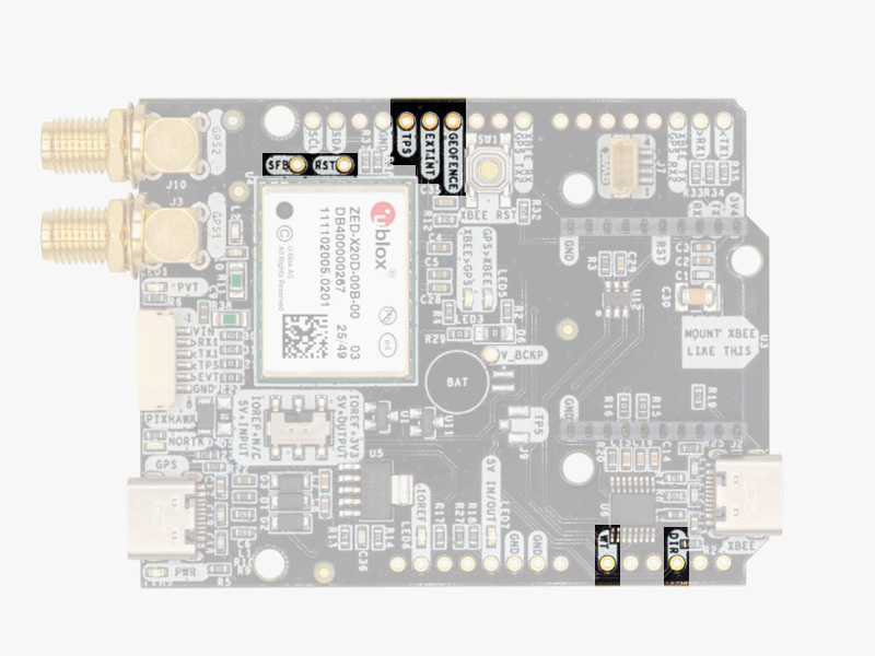
In addition to above, there’s also a few additional pins available for the most advanced users. If you are going to use simpleRTK 4 Dual connected on top of an Arduino or Raspberry Pi and you don’t use any of these pins, it’s recommended to not connect the pins: you can cut the header in this pins to avoid the connection, and prevent unexpected behaviors.
- Timepulse (TPS): 3.3V configuration time pulse output.
- Extint (EXTINT): time synchronization input, maximum voltage 3.6V.
This input is filtered to avoid glitches. - Safeboot (SFB)
- Reset_N (RST)
Remember that you can add a second XBee socket to your board with the Shield for Second XBee socket.
LEDs
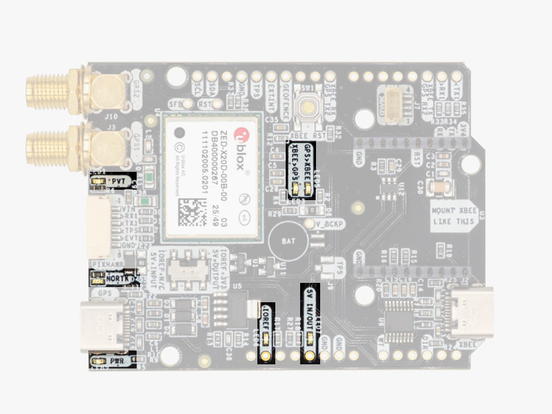
The board includes 7 status LEDs, which indicate that:
- POWER: the simpleRTK4 Dual board has power.
- PVT: LED lights when it was possible to calculate a position from the available satellite visibility.
- NORTK: ON when no RTK, blinking when receiving correction data, OFF when devices is in RTK FIXED mode.
- XBEE>GPS: The XBEE radio is receiving data over the air and sending it to the ZED-X20P.
- GPS>XBEE: The ZED-X20D is outputting data that the XBEE radio is receiving and sending over the air.
- 5V IN/OUT: Will indicate you if there is voltage on that pin.
- IOREF: Will indicate you if the IOREF pin is enabled, which activates the UARTs on arduino rails.
Buttons and switches
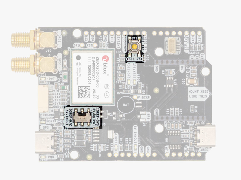
There’s only one button: XBee Reset, and the good news is that you probably will not have to use it. This button is used to program the XBee radio if you want to update firmware, etc.
The switch next to the GPS USB port let you enable IOREF with 3.3V and 5V arduino pin as output so the board can power accessories like Shield for Second XBee socket.
If you need additional information, such as upgrading firmware, configuring the receiver as a base or rover please refer to the u-blox ZED-X20 Configuration Page.
Accessories
You can add any of these features (and more) with our XBee plugins:
-

-
-
- Plugins
Radio module Long Range (LR)
101,00€ This product has multiple variants. The options may be chosen on the product page - Plugins
Radio module eXtra Long Range (XLR)
161,00€ This product has multiple variants. The options may be chosen on the product page -
-
- Sale!Made in Europe
- Sale!Plugins
4G NTRIP Master
156,00€ This product has multiple variants. The options may be chosen on the product page -
- Sale!
-
- Sale!Made in EuropePlugins
PointPerfect L-Band Corrections Receiver NEO-D9S
125,00€Original price was: 125,00€.99,00€Current price is: 99,00€.
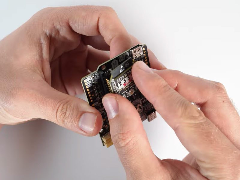
How to add plugin
- To connect the communication plugin to the XBee socket, simply insert it into the XBee connector on the board.
- To use the plugin, go to the u-blox ZED-X20 configuration page and load the configuration file ‘Send NMEA messages to communication plugin’ onto your receiver following the instructions.
