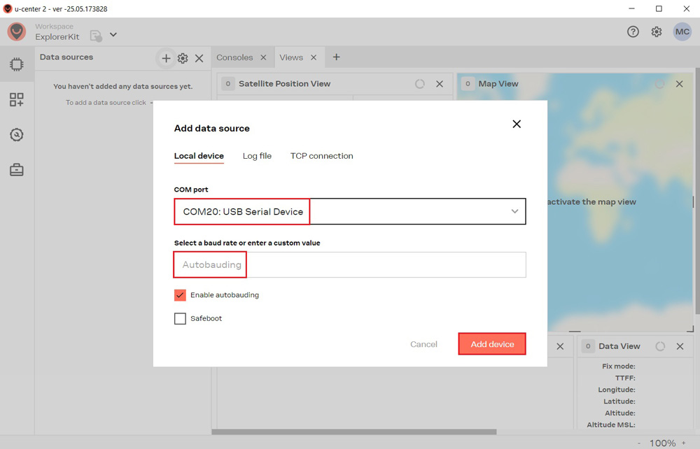
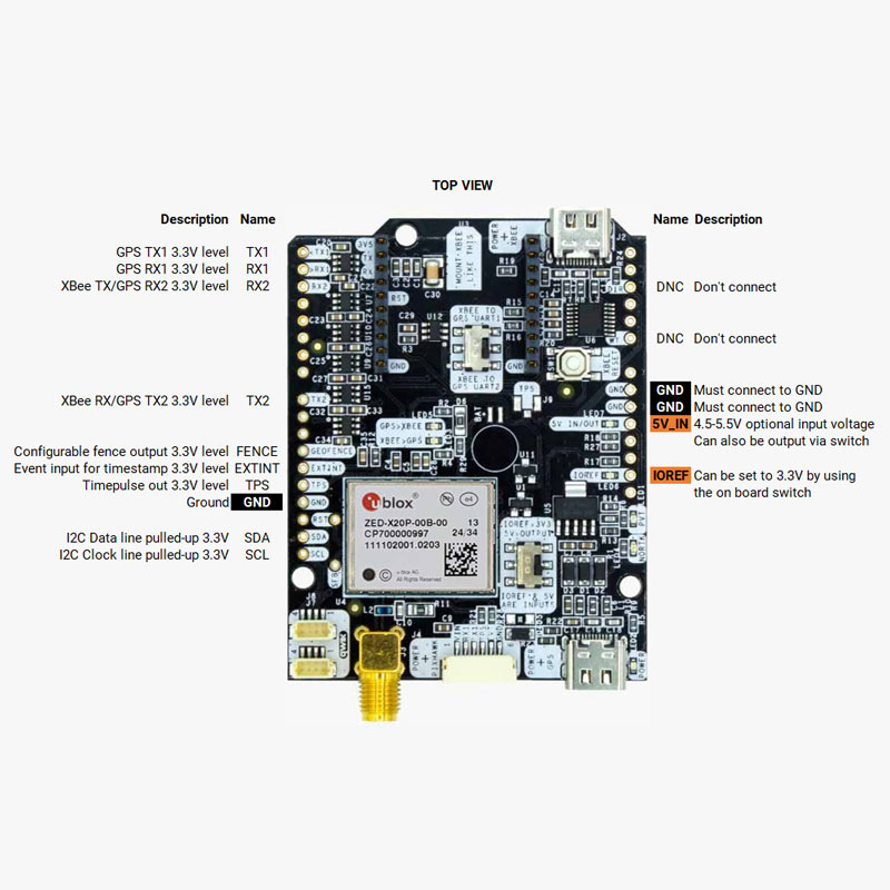
You can use simpleRTK4 Optimum as a independent GNSS receiver by connecting it to your PC or tablet. Additionally, it can be used as an add-on board for your projects, such as an Arduino shield.
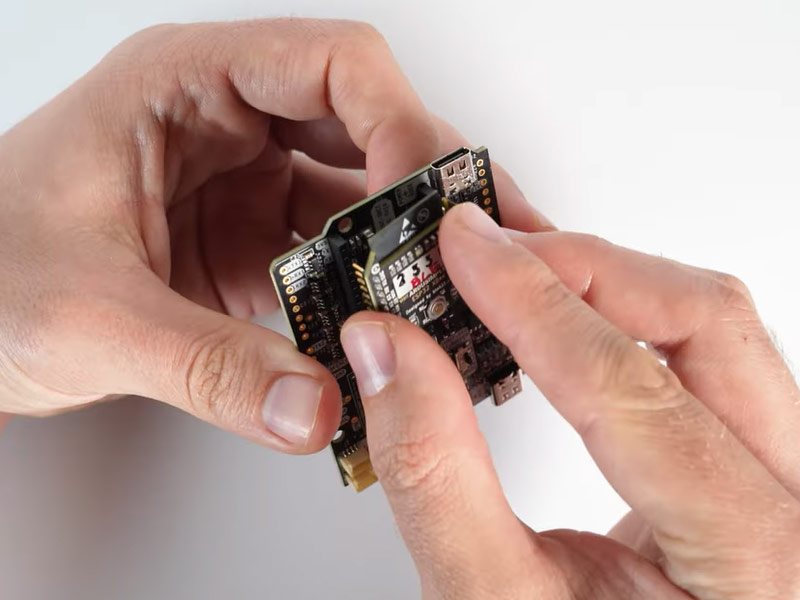
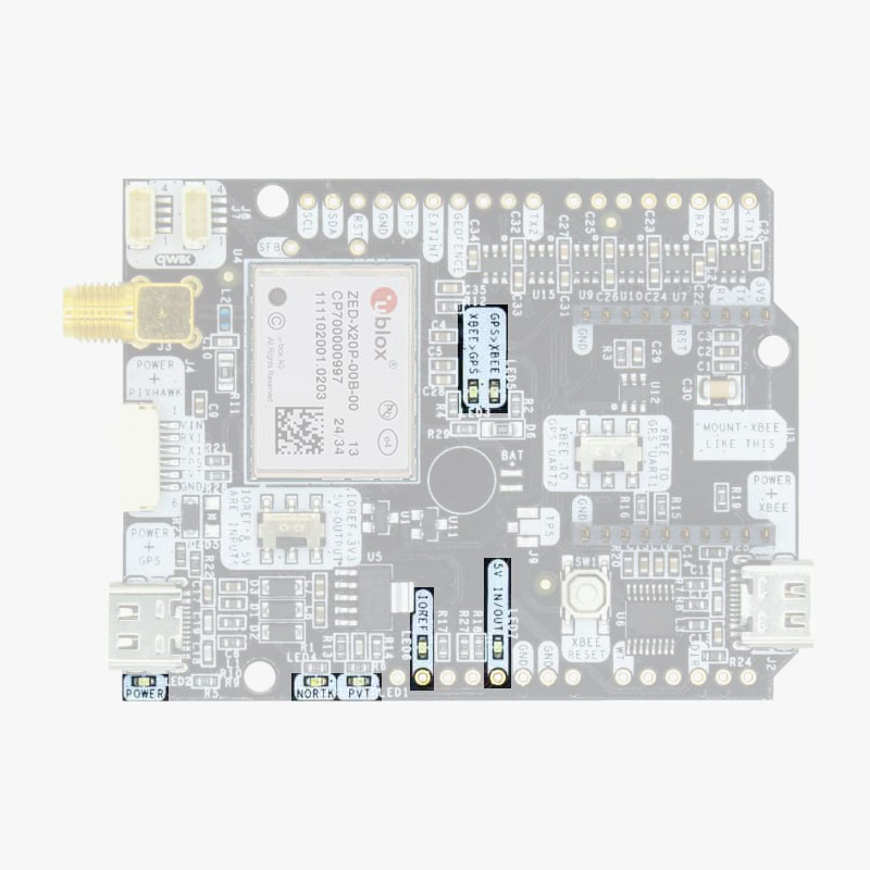
The main component of simpleRTK4 Optimum is u-blox X20 all band (L1/L2/L5 and new L6/E6) RTK GNSS module.
Important before use:
This is a traditional RTK module. It only finds satellites outdoors with good view of the sky. If you try to use it next to the window it won’t work well.
The module needs 10 seconds to boot, be patient after connecting to the PC 🙂
 and
and 

 Plugins
 Plugins
 Made in Europe
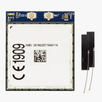 Plugins
 Made in EuropePlugins
 Made in Europe
 Made in EuropeRTK starter kits