 and
and 

User Guide: simpleRTK 4 Heading
Product Overview
In this quick guide, you will learn how to use your simpleRTK 4 Heading board as a standalone unit by connecting it to your PC or tablet. It can also be used as an add-on board for your projects, such as an Arduino shield.
The main component of the simpleRTK 4 Heading is the mosaic‑G5 P3H Triple Band (L1/L2/L5) RTK GNSS module.
Get started
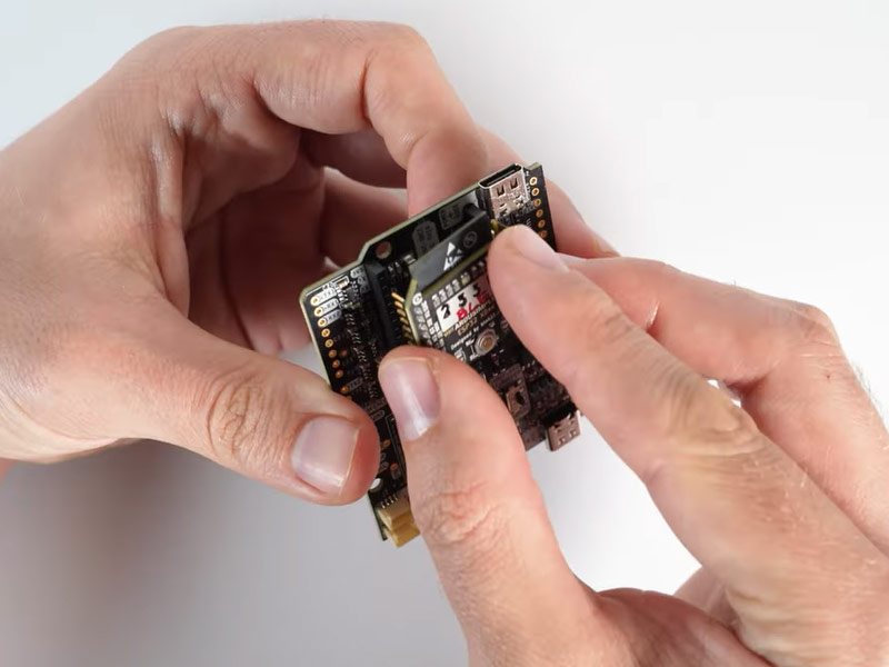
Step A: Assembly and driver installation
Important: This is a traditional RTK module, so it is designed to work outdoors only. It will not function properly if used indoors, even near a window. Additionally, the module requires at least 10 seconds to initialize, so please be patient. 🙂
- Screw the GNSS antenna onto your receiver’s antenna connector by hand; do not use any tools.
- Connect the receiver to your PC using the USB port labeled POWER+GPS.
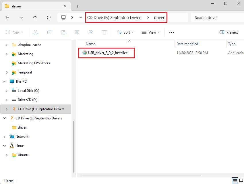
- When you connect this product to a PC for the first time, it may not be recognized immediately. You may see only a new drive appear on your computer. Open this drive and install the provided Septentrio driver.
- Once the driver installation is complete, disconnect and reconnect the receiver to your PC. After this, your computer will recognize the receiver. This step only needs to be done once.
- Next, download and install the RxTools Software suite for your operating system (this guide uses Microsoft Windows as an example). This will install several applications in your computer, but for this guide we will use only the RxControl application. Its intuitive graphical user interface (GUI) allows you to control your Septentrio receiver, perform data logging, and monitor the navigation solution.
Step B: Connect to RxControl
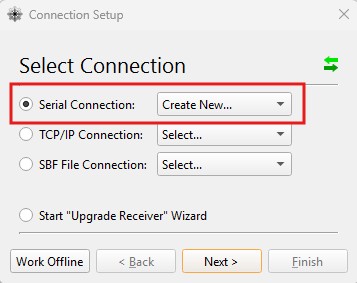
- Open the RxControl app and create a new Serial Connection. Press Next.
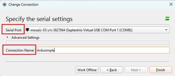
- Specify the computer’s Serial Port you want to use to connect to your mosaic-G5 receiver, enter a Connection Name, and then press Finish.
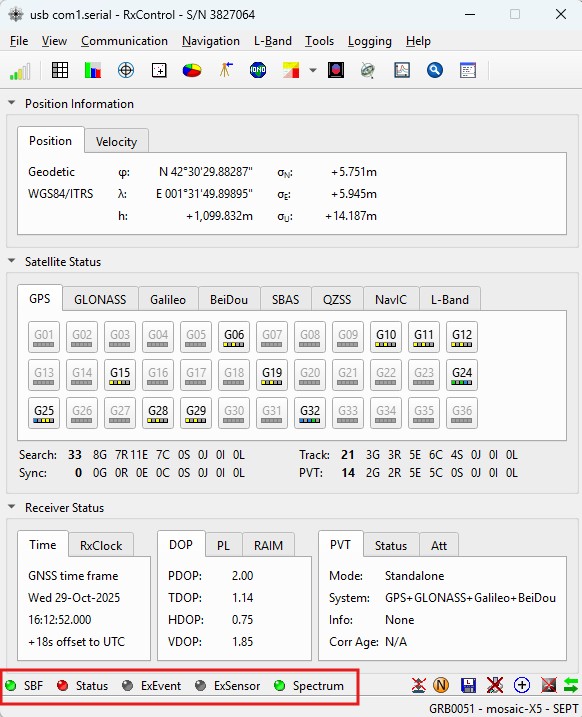
- Upon opening, the RxControl GUI will display a Status Bar at the bottom. This bar shows the connection status, with blinking indicator lights confirming both the active link to your receiver and that data is streaming from it.
Step C: RTK corrections
Follow the steps in this user manual to achieve centimeter/millimeter-level accuracy with our GNSS receivers, which requires RTK corrections. The easiest way to get corrections is to use an RTK correction service available in your region. To help you get started, we have prepared a list of RTK correction services in your country.
Before you begin, ensure:
- You have registered for an RTK correction service and received the necessary credentials (server address, port, username, and password) to connect to it.
- Your PC has an active internet connection to access the NTRIP service.
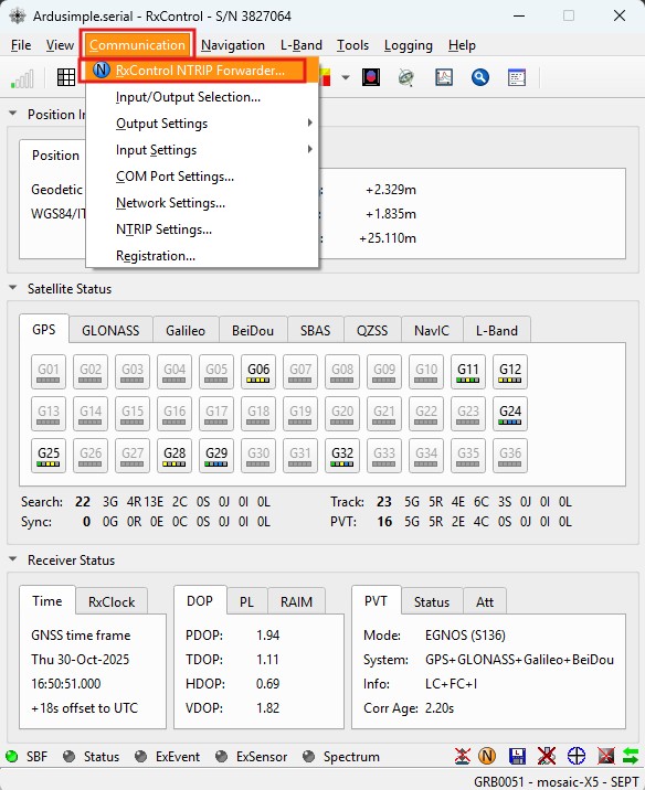
- Go to main menu Communication -> RxControl NTRIP Forwarder…
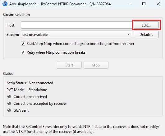
- It will bring up the Ntrip Forwarder dialog. Press Edit.
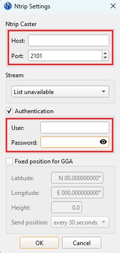
- In the Ntrip Settings dialog, fill in the required caster settings: Host, Port, username and password for your NTRIP account. This information is provided by your NTRIP service upon registration. Press OK.
- If the NTRIP account credentials were entered correctly, the Stream drop-down list will become active, and you can select your RTK correction Mount Point. Then, press Start.
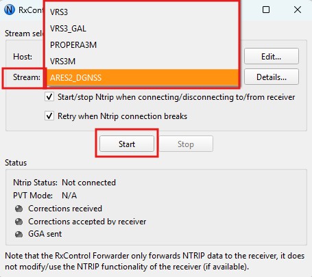
- If the connection is successful, the Status field in the NTRIP Settings dialog should indicate that a connection has been established and that correction data is being received.

- After a few minutes, the PVT Mode should change to RTK Float or RTK Fixed, indicating that your receiver has now achieved centimeter/millimeter-level accuracy.

Step D: Heading configuration
Follow this dual-antenna installation manual to obtain correct heading data from the mosaic‑G5 P3H module.
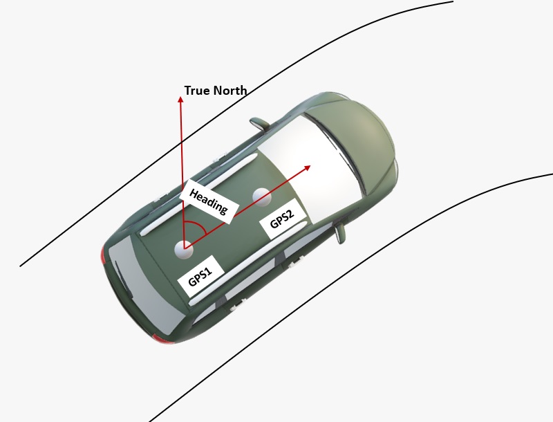
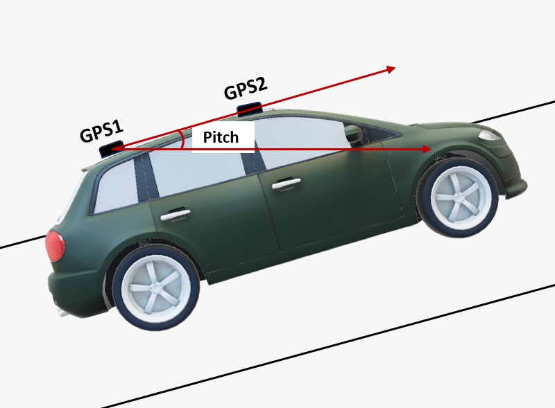
- The heading result is the clockwise angle from True North to the baseline that runs from the master antenna (labeled GPS1 on the board) to the slave antenna (labeled GPS2). The pitch angle refers to the angle of the vehicle or drone relative to the horizontal plane.
- By default, the antennas should be installed longitudinally along the vehicle, with the master antenna (GPS1) positioned at the rear.
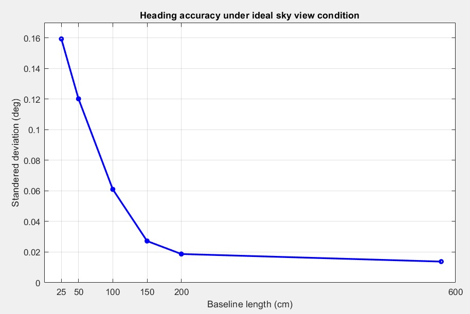
- A minimum distance is required between the two antennas for accurate heading calculations. Heading accuracy improves with a longer baseline (the distance between the antennas).
A baseline of at least 1 meter is generally required to achieve satisfactory sub-degree precision under non‑ideal conditions. However, for many vehicles, this is not practical.
With a high‑quality installation and a 0.5‑meter baseline, you can achieve decent results. At 0.3 meters, it is possible to obtain a heading, but the output may be somewhat noisy.
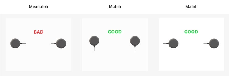
- For best performance, both GNSS antennas should be identical and oriented in the same direction relative to each other. For example, the antenna cables should exit from the same side on both units. This ensures the best alignment of the RF phase centers, which is critical for heading accuracy (note that the actual RF phase center is often offset from the antenna’s physical center).
Additionally, the RF cable lengths for both antennas must be identical to achieve optimal results.
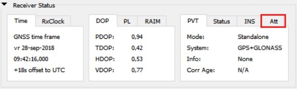
- Open Septentrio RxTools. The main window will display the Attitude tab under the Receiver Status section, which provides GNSS-based heading and attitude information.
Mode: The current GNSS heading/attitude mode.
Error1: The current error status for auxiliary antenna 1.
Error2: The current error status for auxiliary antenna 2.
Nr SV: The average number of satellites, calculated across all antennas, currently being used in the attitude calculations.
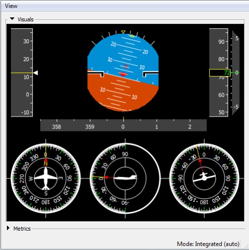
- At View -> Attitude View you can check the heading information of the vehicle. Below the Velocity Attitude Indicator, a series of dials (from left to right) display the Heading (including a secondary green/cyan indicator for the course over ground), Pitch and Roll.
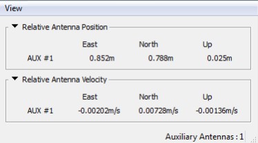
- The View -> Auxiliary Antennas View displays the position of the auxiliary antenna relative to the main antenna, as well as their velocities. Both position and velocity are provided in the East, North, and Up (ENU) coordinate frame.
Hardware
Pinout
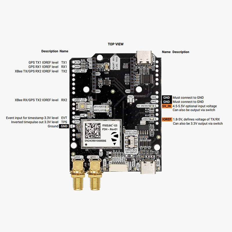
Power
The simpleRTK 4 Heading can be powered from 4 different sources:
- GPS USB port
- XBEE USB port
- Pixhawk connector
- Arduino rail
Only 1 of them is needed to use the board, but you can also connect the 4 at the same time, there’s no risk.
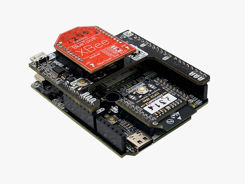
The simpleRTK 4 Heading has a High Power (HP) XBee socket. You can connect any XBee accessory to it.
If you connect a device that requires high power to the XBee socket, you will have to make sure your power supply can provide this power.
- Use only high quality USB-C cables, not longer than 1 meter.
- If you connect simpleRTK 4 Heading through a USB hub to your PC/Tablet or your PC has low power USB ports, you will have to connect the second USB port directly to a wall plug or high power USB port.
GNSS Antennas
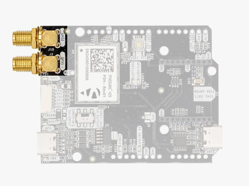
The simpleRTK 4 Heading does not include, but requires a pair of high-quality GPS/GNSS triple band (L1/L2/L5) antennas. In order to get the best performance we recommend using our Triple Band simpleANT3B series antenna.
The board is compatible with both active antennas (maximum output is 150mA @ 3.3V) and passive antennas.
Installation Notes:
- Always connect the antennas before powering the board. This is very important as some board components could overheat if no antenna is connected.
- Screw the antenna to the SMA connector by hand, never use any tools. You could break the connectors if too much force is applied.
- Install the antennas with the clearest possible view of the sky. Use it outdoors and as far as possible from surrounding buildings, mountains, …
- For best results, install the antennas on top of a metallic flat plate of at least 20cm side lenght (e.g. a car top surface).
- In the default configuration, the antennas should be placed longitudinally along the vehicle, with the master antenna (GPS1) positioned at the rear.
- Heading accuracy depends on the distance between the antennas (see the image below). With a high-quality installation at a 0.5-meter baseline, you can achieve decent results.
For more information on how antenna installation impacts performance, follow our GPS/GNSS antenna installation guide and video.
Interfaces
The simpleRTK 4 Heading board has a few interfaces that we will now explain in detail.
USB GPS
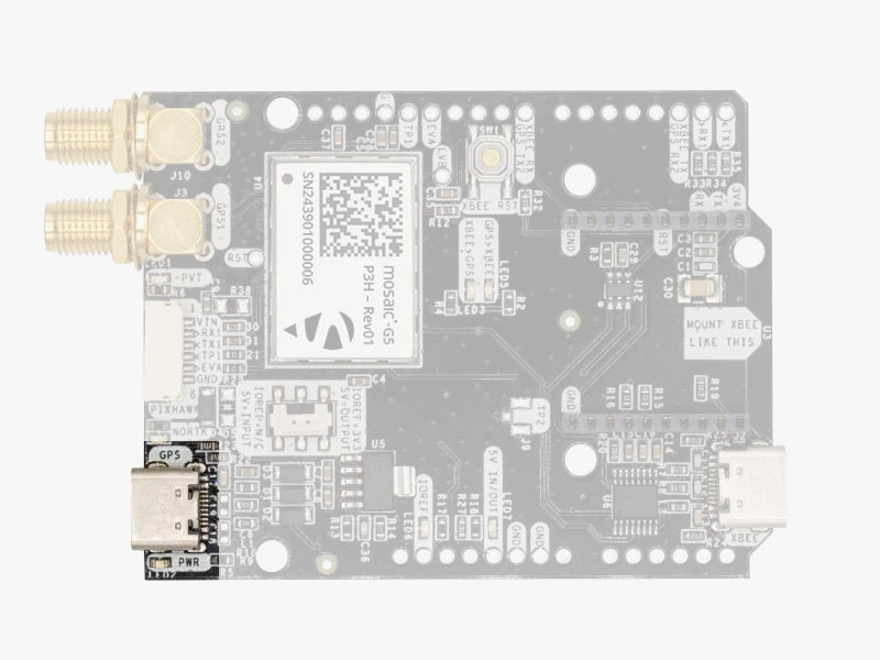
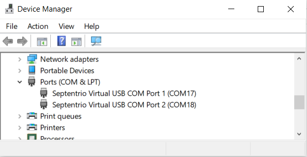
This USB-C connector gives you access to the native USB from the mosaic-G5 P3H. When you connect to the PC for the first time, you will only see a new Hard Disk in your computer. Open it and install the Septentrio drivers.
After installation, when you connect the receiver to the PC you will see 2 new COM ports, that you can use with your favourite terminal tool to read NMEA, or configure and monitor the receiver using RxTools.
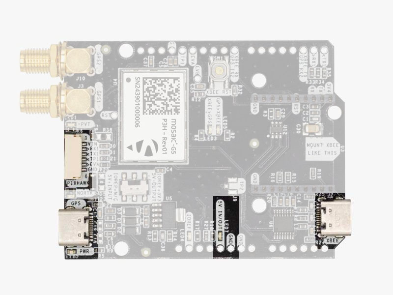
USB XBee
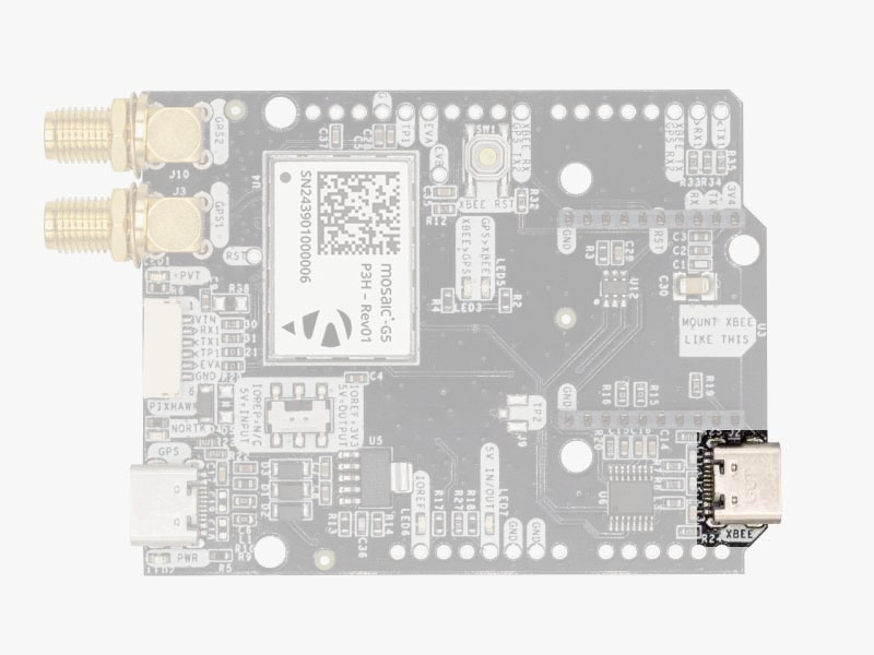
This USB-C connector gives you access to the UART of the XBEE radio (if you mount one), via an FTDI USB-to-UART converter.
We find very practical to use this connector to power the board, so you can then connect and disconnect the GPS USB as your wish, without removing the power to the board.
You can use any USB wall plug adapter you find at home.
To use this connector only as a power source, you don’t need any driver. You can use your PC, or connect to your USB wall adapter.
To use this connector to configure an XBee radio, you will need the VCP driver from FTDI: https://ftdichip.com/drivers/vcp-drivers/
Pixhawk connector
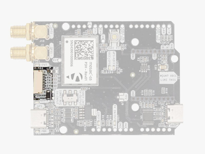
This connector is a standard JST-GH that can be used to connect the simpleRTK 4 Heading to a Pixhawk autopilot.
You can also use this connector to power the board.
The Pixhawk JST-GH connector is following the Pixhawk standard:
- 1: 5V_IN
- 2: Mosaic COM1 RX (3.3V level)
- 3: Mosaic COM1 TX (3.3V level)
- 4: Timepulse output (3.3V level)
- 5: Event input (3.3V level)
- 6: GND
Please note that the board only includes GPS and doesn’t include magnetometer.
Arduino rails
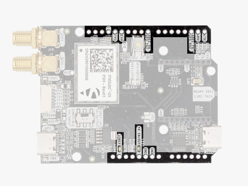
simpleRTK 4 Heading has optional rails to connect to other arduino UNO compatible devices.
- GND: ground is available in the standard arduino pins. You should always connect this line to your other board.
- 5V IN/OUT:
- When the LED next to this pin is OFF, can power simpleRTK 4 Heading from this pin.
For example, just plug it on top of an Arduino UNO board, and simpleRTK 4 Heading will turn ON. (check if your arduino can power 300mA @ 5V shields). - Alternatively, you can now use simpleRTK 4 Heading to power other shields.
Just turn ON the switch “5V=OUTPUT” and simpleRTK 4 Heading board will output 5V at this pin.
- When the LED next to this pin is OFF, can power simpleRTK 4 Heading from this pin.
- IOREF. This pins affect the functionality of TX1,RX1,TX2,RX2 pins.
- When plugging simpleRTK3B Heading board on top of Arduino UNO or Raspberry Pi, this pin is used to automatically defined the voltage level of the communication pins (TX1,RX1,TX2,RX2).
- When wiring your own cables to board, this is an input that will define the voltage levels of the pins.
If you input 1.8V, the next pins will be 1.8V level. It supports from 1.2V to 5.5V. - If you want to connect wires to the listed pins and 3.3V is OK for you, you just need to enable the switch “IOREF=3.3V”
- TX1,RX1,TX2,RX2: These pins work with the voltage level defined by IOREF.
- TX1: Mosaic COM1 TX
- RX1: Mosaic COM1 RX
- TX2: XBee UART TX (this pin is also connected to Mosaic COM2 RX).
- RX2: XBee UART RX (this pin is also connected to Mosaic COM2 TX).
High Power (HP) XBee socket
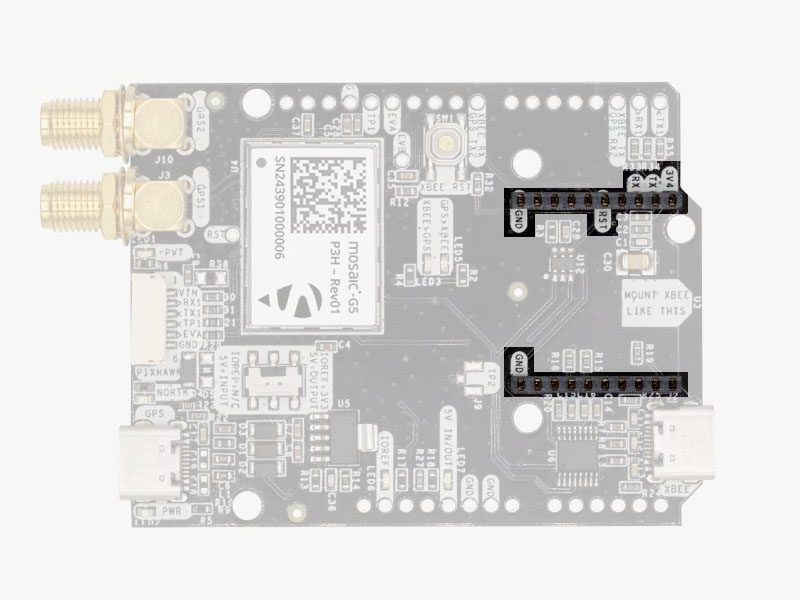
The simpleRTK 4 Heading has a High Power (HP) XBee socket. You can use this socket to connect an XBee compatible radio. The following pins are available:
- VCC, which is a 3.3V output with maximum current 1A constant and peak 1.5A.
- XBee UART RX, at 3.3V level
- XBee UART TX, at 3.3V level
- GND
The XBee socket is connected to Mosaic COM2.
Special function pins
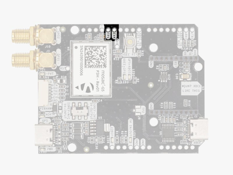
In addition to above, there’s also a few additional pins available for the most advanced users. If you are going to use simpleRTK 4 Heading connected on top of an Arduino or Raspberry Pi and you don’t use any of these pins, it’s recommended to not connect the pins: you can cut the header in this pins to avoid the connection, and prevent unexpected behaviors.
- Timepulse (TPS): 3.3V configuration time pulse output. The logic of this pin is inverted with the web interface. If the web interface you select HIGH, the pin will output LOW.
- External Event (EVT): time synchronization input, maximum voltage 3.6V. This input is filtered to avoid glitches.
Remember that you can add a second XBee socket to your board with the Shield for Second XBee socket.
LEDs
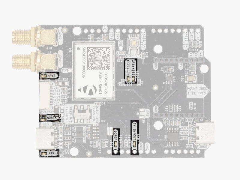
The board includes 7 status LEDs, which indicate that:
- POWER: the simpleRTK 4 Heading board has power.
- PVT: LED lights when it was possible to calculate a position from the available satellite visibility.
- NORTK: ON when no RTK, blinking when receiving correction data, OFF when devices is in RTK FIXED mode.
- XBEE>GPS: The XBEE radio is receiving data over the air and sending it to the Mosaic.
- GPS>XBEE: The Mosaic is outputting data that the XBEE radio is receiving and sending over the air.
- 5V IN/OUT: Will indicate you if there is voltage on that pin.
- IOREF: Will indicate you if the IOREF pin is enabled, which activates the UARTs on arduino rails.
Buttons and switches
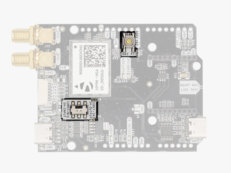
There’s only one button: XBee Reset, and the good news is that you probably will not have to use it. This button is used to program the XBee radio if you want to update firmware, etc.
You will find also 1 switch under the XBee socket: it let you enable IOREF with 3.3V and 5V arduino pin as output so the board can power accessories like Shield for Second XBee socket.
At the same time this switch will also enable the arduino rail signals at 3.3V. Check the “Arduino Rails” section above to read more details about this.
If you need additional information beyond this integration guide, such as upgrading firmware, configuring the receiver as a base or rover please refer to the Septentrio Mosaic-G5 Configuration Page.
Accessories
You can add any of these features (and more) with our XBee plugins:
-

-
-
- Plugins
Radio module Long Range (LR)
101,00€ This product has multiple variants. The options may be chosen on the product page - Plugins
Radio module eXtra Long Range (XLR)
161,00€ This product has multiple variants. The options may be chosen on the product page -
-
- Sale!Made in Europe
- Sale!Plugins
4G NTRIP Master
156,00€ This product has multiple variants. The options may be chosen on the product page -
- Sale!
-
- Sale!Made in EuropePlugins
PointPerfect L-Band Corrections Receiver NEO-D9S
125,00€Original price was: 125,00€.99,00€Current price is: 99,00€.
How to add plugin
- To connect the communication plugin to the XBee socket, simply insert it into the XBee connector on the board.
- To use the plugin, go to the How to configure Septentrio mosaic-G5 P3 and P3H page and load the configuration file Send 1Hz full NMEA to Plugin onto your receiver following the instructions.
- The board supports a second XBee plugin. You can use two communication plugins at the same time by adding a Shield for Second Plugin Socket. To attach it, you will need the Expansion Headers Kit (not soldered) on the receiver, or order Expansion Headers Kit (soldered) if you want us to solder it for you.
- Sale!Made in EuropeRTK4 Boards
simpleRTK 4 Heading
519,00€Original price was: 519,00€.499,00€Current price is: 499,00€.
