 and
and 

How to configure simpleRTK2B Heading – Basic Starter Kit and connect it to ArduPilot

Looking at the official Ardupilot forum we found many users having problems configuring their simpleRTK2B Heading with their ArduPilot. After some testing we prepared this tutorial to make the process easier.
In case you have simpleRTK3B Heading, we have prepared a tutorial How to configure triple-band Septentrio GNSS receiver and connect it to ArduPilot.
If you plan to send RTK corrections from your ground control station to your simpleRTK2B Heading Kit, refer to ArduSimple tutorial How to connect simpleRTK2B Heading to ArduPilot with external RTK corrections.
Required hardware:
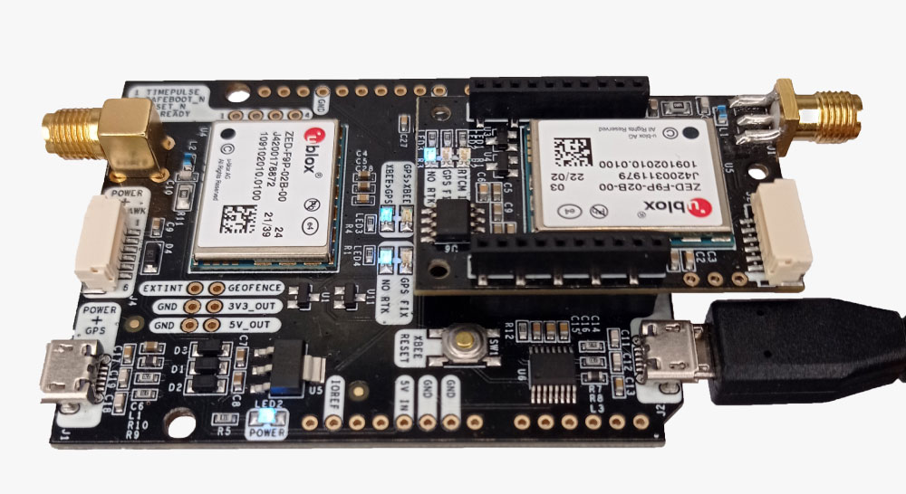
- simpleRTK2B Heading – Basic Starter Kit
- USB to micro-USB cable
- Pixhawk cable set
- Holybro Pixhawk 4 (you can also use your preferred autopilot)
- a PC or laptop
Required software:
- Mission Planner
- u-center ( for M8, M9, F9)
Important things before start:
- This tutorial is based on the simpleRTK2B Heading Basic Starter Kit, if you have a different hardware you may need to apply some changes in this tutorial.
We have prepared another tutorial for the simpleRTK3B Heading. - We have validated the tutorial with these autopilots:
- Holybro Pixhawk 4
- mRo Pixhawk Flight Controller (aka Pixhawk 1)
- We have validated the tutorial with these firmware versions:
- ArduRover 4.1.0-dev
- ArduCopter 4.1.0-dev
- ArduPlane 4.1.0-dev
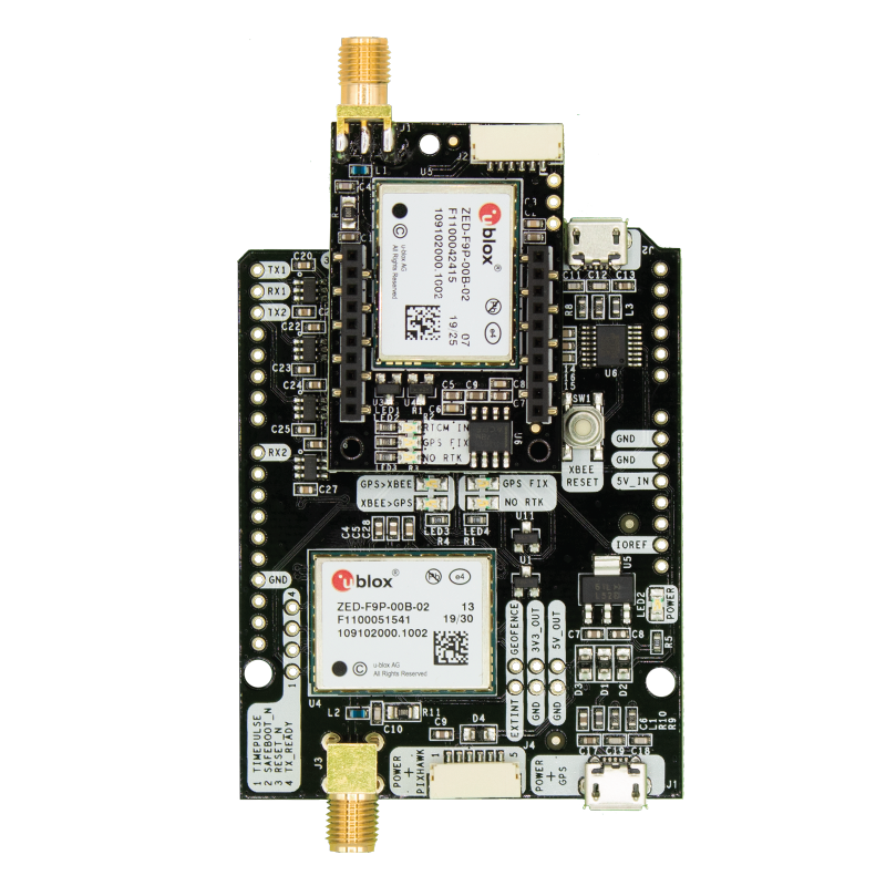
- In the simpleRTK2B+heading Basic Starter Kit:
- simpleRTK2B (big board) acts as a rover in the moving base configuration
- simpleRTK2Blite (small board) acts as a base in the moving base configuration
- This tutorial works on firmware 1.13 of ZED-F9P.
How to configure simpleRTK2B Heading with ArduPilot?
Firstly, configure simpleRTK2B Budget receiver (aka big board).
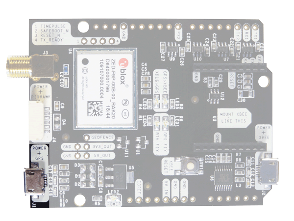
- Connect the big board to your PC via the USB port labeled as POWER+GPS with a micro-USB cable.
- Run u-center and connect your receiver to u-center via com port.

- The big board acts as a rover in the moving base configuration.
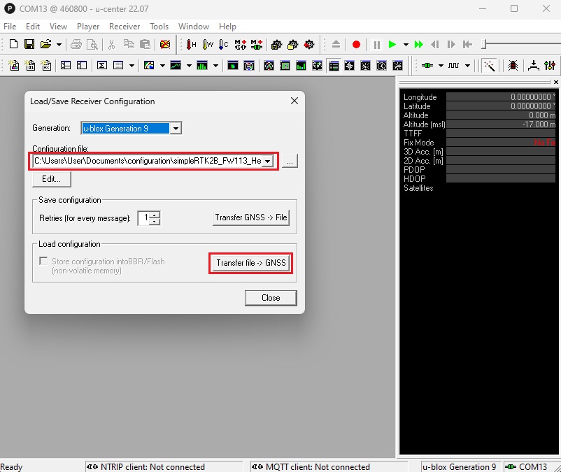
Go to Tools–>Receiver Configuration…–>Select configuration file simpleRTK2B_FW113_HeadingKit_Rover_10Hz_Ardupilot.txt (right click and select save link as).
The configurations files for the GNSS receivers will set them at an output rate of 10Hz, with UBX-RELPOSNED and UBX-PVT sent to the autopilot.
- Click Transfer file–>GNSS.
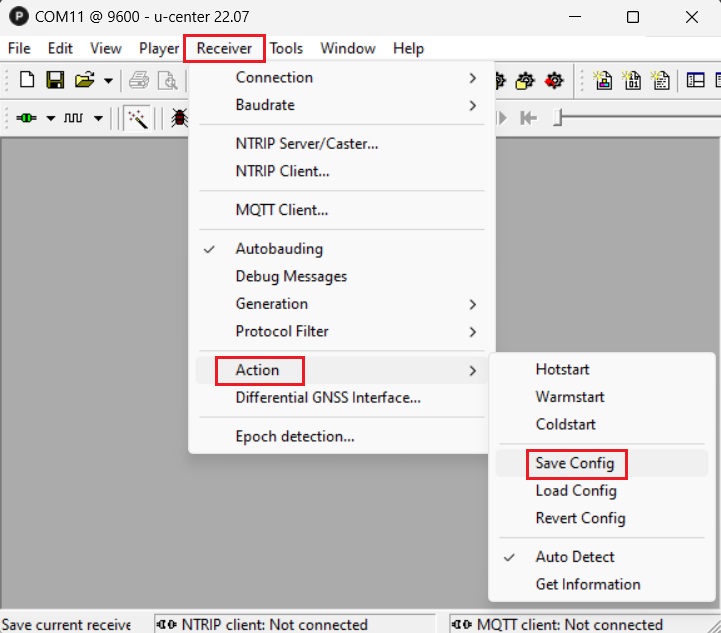
- In the menu bar, go to Receiver–>Action–>Save Config to save your configuration.
Secondly, configure simpleRTK2B Lite receiver (aka small board).
- Make sure the simpleRTK2B Lite board is mounted on top of the simpleRTK2B board.
- Connect the simpleRTK2B Lite to your PC via the USB port labeled as POWER+XBEE with a micro-USB cable.
- Run u-center and connect your receiver via COM port.
- Go to Tools–>Receiver Configuration…–>Select configuration file simpleRTK2B_FW113_HeadingKit_MovingBase_10Hz_Ardupilot.txt (right click and select save link as).
Click Transfer file–>GNSS.Note that depending on your previous configuration, you may need to upload the configuration file twice because there is a baud rate change in the middle of the configuration file. First at the baudrate at which you can communicate with the board, and second time at 460’800.
- In the menu bar, go to Receiver–>Action–>Save Config to save your configuration.
Thirdly, load ArduPilot configuration file.
- Connect your Pixhawk to your computer using a USB to micro-USB cable.
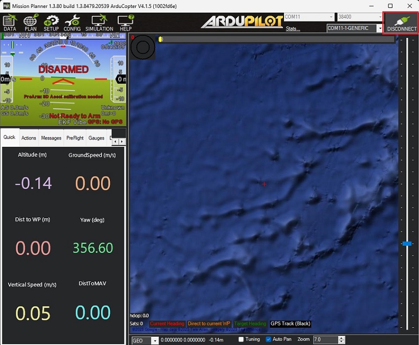
- Open Mission Planner and connect your Pixhawk to it with COM port.
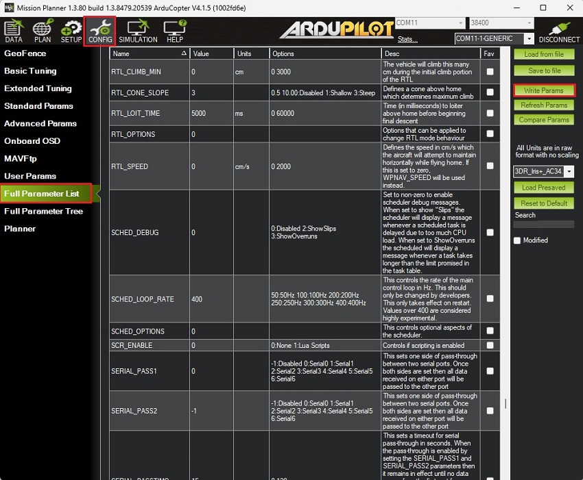
- Go to CONFIG–>Full Parameter List.
Given that the firmware versions might differ from yours, below is a list of all parameters that have been modified compared to the default configuration:
- Go to CONFIG–>Full Parameter List.
COMPASS_ENABLE,0
COMPASS_USE,0
COMPASS_USE2,0
COMPASS_USE3,0
EK3_MAG_CAL,5
EK3_SRC1_YAW,2
GPS_AUTO_CONFIG,0
GPS_AUTO_SWITCH,0
GPS_POS1_X,-1.25 *This value must contain the distance in meters between antennas. Change sign if heading has a 180deg offset (or swap SMA connectors in simpleRTK2B+heading).
GPS_PRIMARY,1
GPS_RATE_MS, 100
GPS_RATE_MS2, 100
GPS_TYPE,0
GPS_TYPE2,18
SERIAL1_BAUD,460
SERIAL1_OPTIONS,0
SERIAL1_PROTOCOL,5
Press Write Params to save your setting.
- After saving all the parameters, make sure you remove the power from your autopilot by disconnecting USB cable to reset your autopilot.
Finally, connect the heading kit to your autopilot.
- Make sure your already finish the initial setup of your autopilot. You can check the user guide of ArduPilot to see how to do it.
- Use the JST connector on the simpleRTK2B (big board) and connect it to the TELEM1 port.
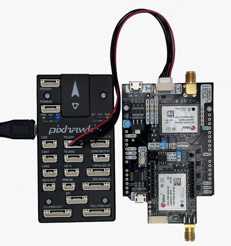
- Connect the antennas to your receiver. Make sure your antennas are completely in open air.
Note that if:- Fix type is not RTK fix
- Antenna distance is not within 20% of the GPS1_POS_X parameter
- Autopilot attitude does not match antenna height difference
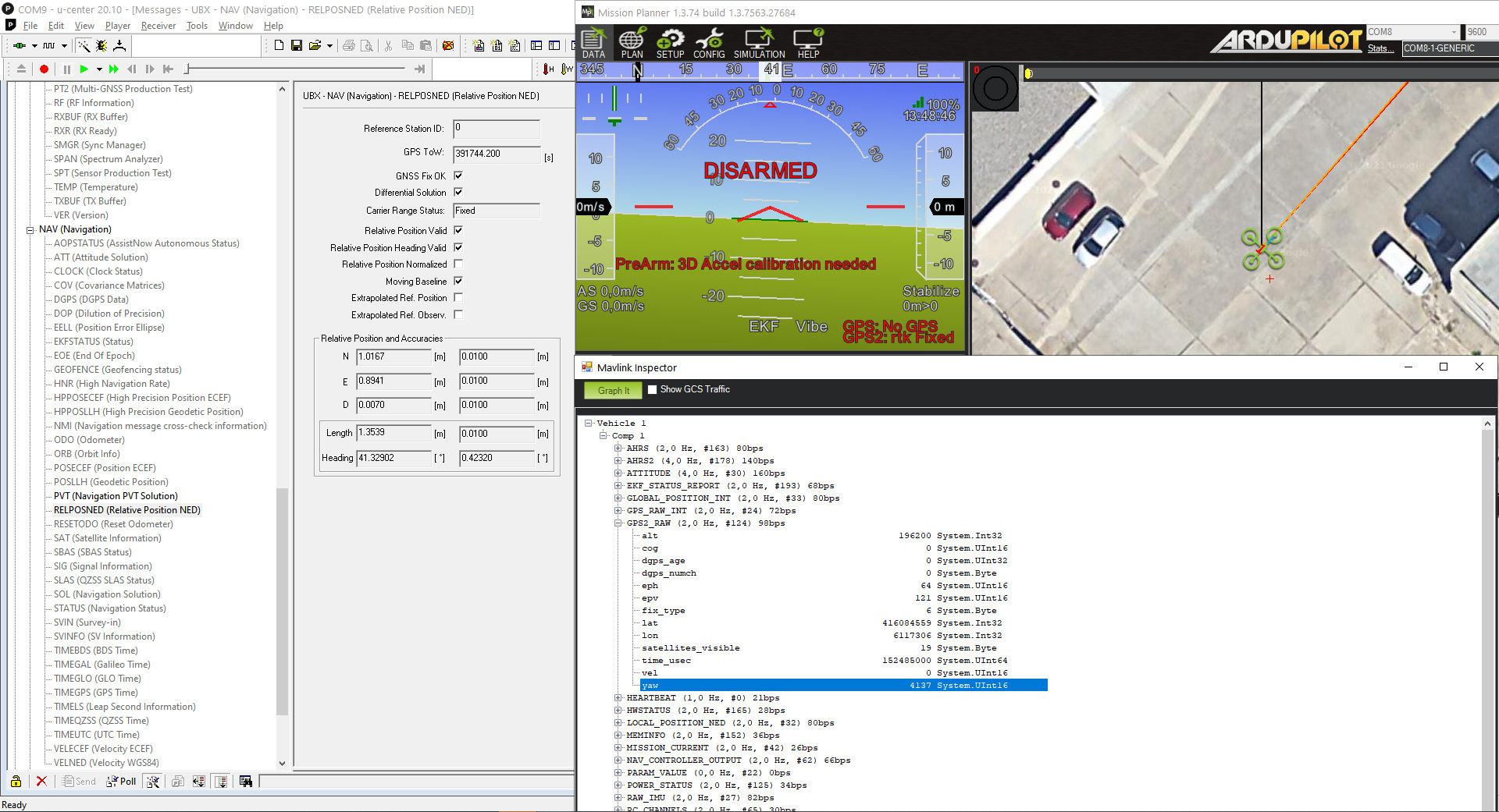
- Power the autopilot and wait a few seconds. Check the AHRS heading value on Mission Planner, it should match the direction between your antennas.
You can also check the Heading value of your antennas using u-center by following View–>Messages View–>UBX–>NAV–>RELPOSNED in the software.
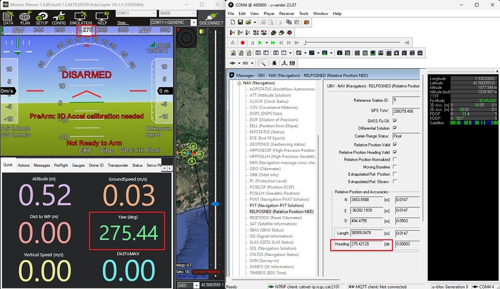
- For an additional verification, ensure that the heading value in the AHRS matches the one found in CTRL+F–>MAVlink inspector–>GPS2_RAW–>yaw.
- Congratulations! Now you can use your Heading Kit on your ArduPilot.

RTK Assistant
Find the best products for your application in just a few questions.

