and
and 


Auto
Geodetic
Auto
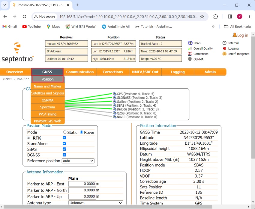
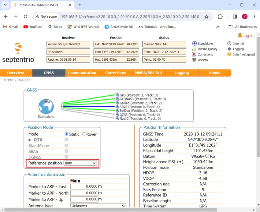
- In the Position Mode window, at Reference position choose auto.

Geodetic
- Write down the static position of your antenna which you obtained using the 3 methods mentioned above.
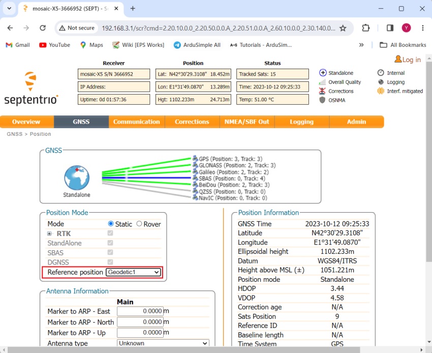
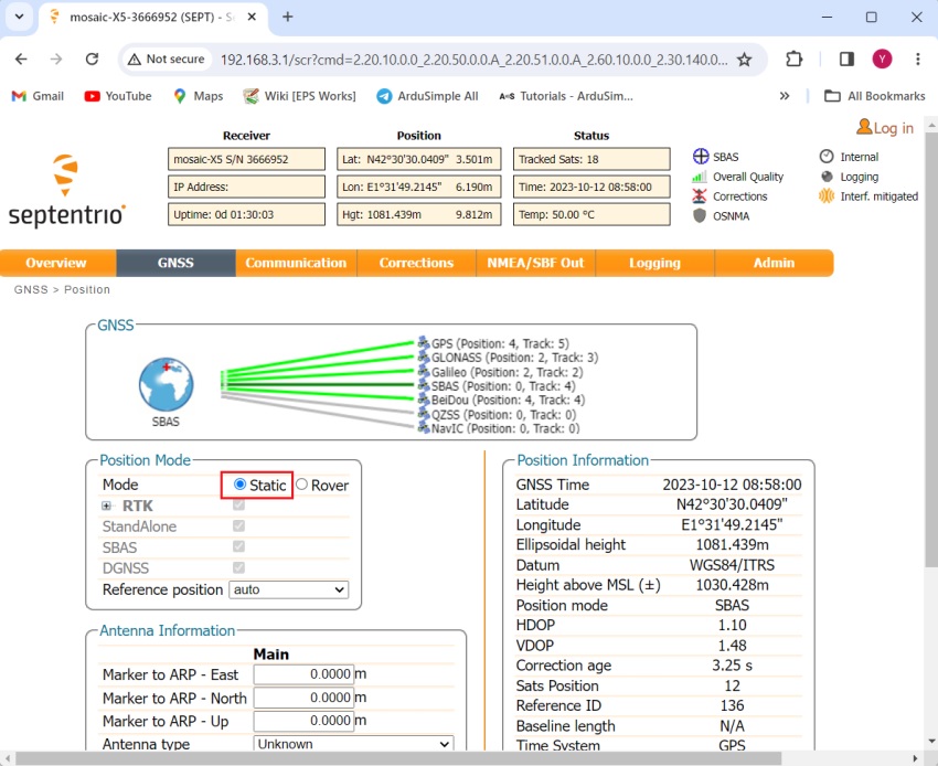
- In the Position Mode window, at Reference position select Geodetic 1.

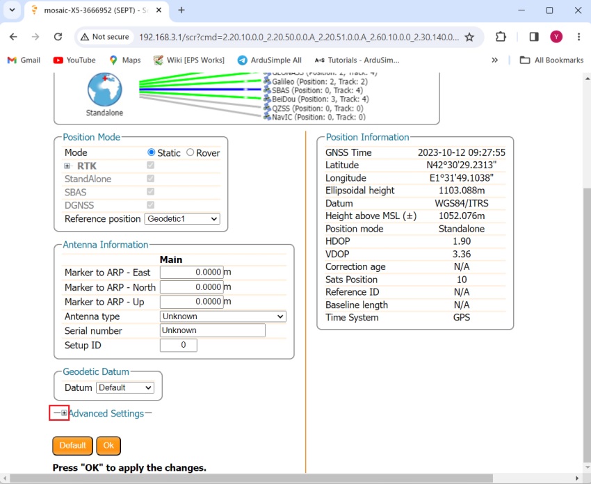
- Now scroll down and expand the “Advanced Settings”.
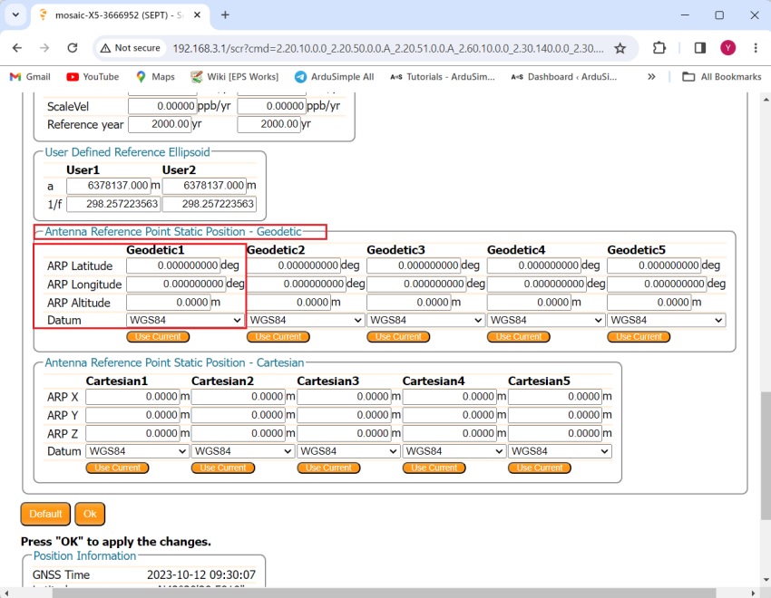
- Continue scrolling down until you find Antenna Reference Point Static Position – Geodetic. Set your known latitude, longitude and altitude. If you use a custom datum also define it here.Note that the altitude to be set is the ellipsoid altitude (if you need more info about different types of altitudes you can check out tutorial about gnss altitudes).