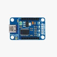
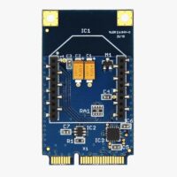
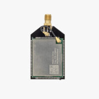
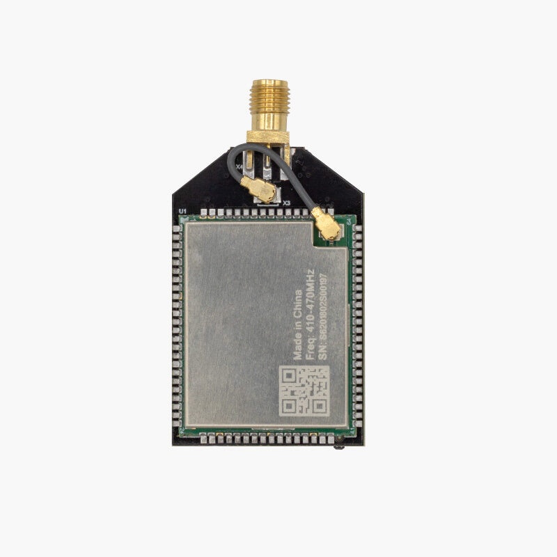
The ArduSimple 450MHz Radio Module is a compact UHF data radio in XBee form factor, based on the Ebyte RD400D transceiver. It operates in the 410–470 MHz band and is optimised for sending GNSS correction data over the air in surveying, precision agriculture and drone applications.
The module connects directly to any board via the standard XBee socket — no additional wiring or adaptors needed. The 450MHz Radio Module can be used in two different ways:
Radio module comes pre-configured to send corrections over the air at 19200 bps in low power mode (27 dBm) and allowing frequencies from 433.050 to 434.790 MHz matching european regulation.
Simply plug onto your base and rover ArduSimple boards and they will synchronize with each other automatically at up to 5.6 km in open sky conditions.
Configurable via serial commands — frequency, power, protocol and baud rate.
Half-duplex operation — point-to-point and point-to-multipoint supported.
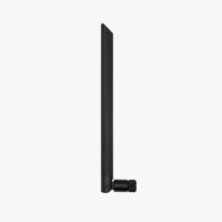
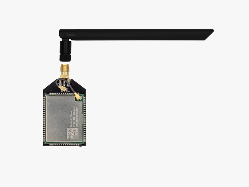
The 450MHz Radio module can be connected to any dipole antenna, but a specific 450MHz antenna is required for best performance. The antenna should include an SMA female connector for connection. Cable antennas are useful if you want to keep the radio module indoor while the antenna is placed outdoors.
Align and screw the dipole antenna SMA connector to the radio module antenna connector by hand, do not use any tools as overtightening it might damage the module.
Always make sure to have the antenna connected before powering the radio module, otherwise it might overheat and get damaged.
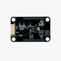
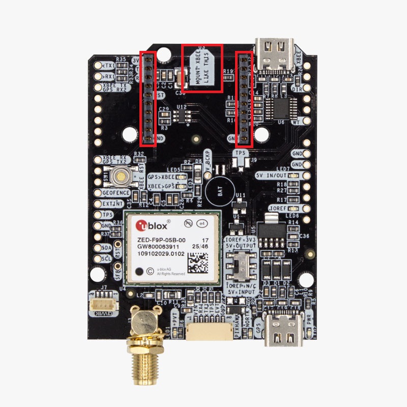
Orient the radio module board with the label MOUNT XBEE LIKE THIS (diamond shape) of the hosting board, and align the pins with its corresponding holes of the XBee socket headers.
Insert the radio module in the XBee socket.
Step C: Power the radio module
To start using the radio module just power the hosting board:
By any of the power sources available on your RTK board, please check its specifications for power limitations.
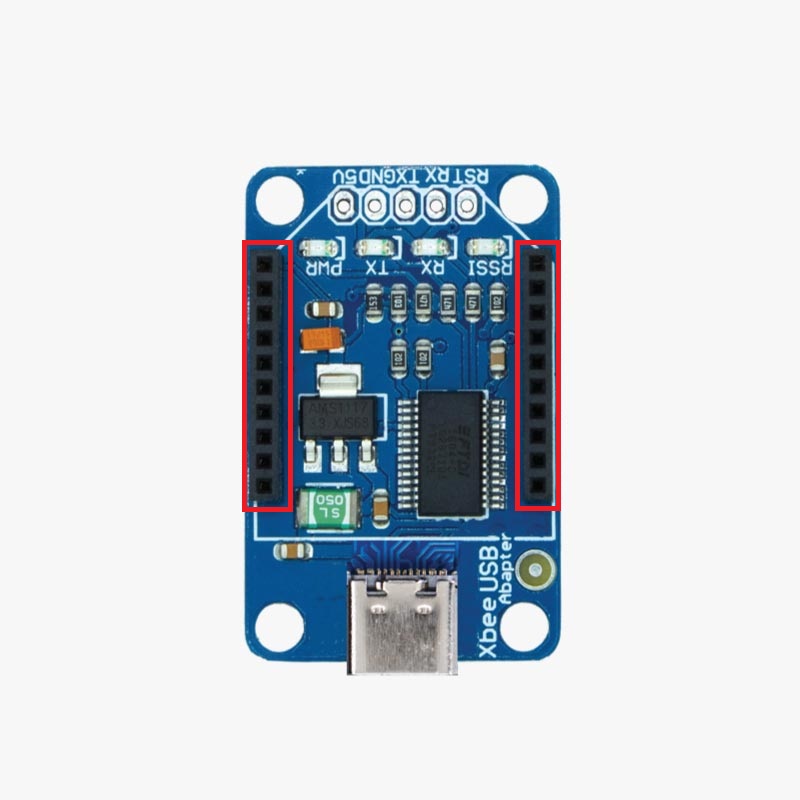
By connecting the carrier board USB port to a computer.
Once powered the XBee interface is fully transparent: data written to the serial port is transmitted over the air and delivered to the receiving unit unchanged.
Power level is configurable for compliance with regional regulations. Frequency, protocol and baud rate can be changed via serial commands using any serial terminal, please check the Configuration section of this guide.
Connect the USB-C cable to the RTK board (USB port beside the XBee interface) or carrier board, and the other end to a Windows PC.
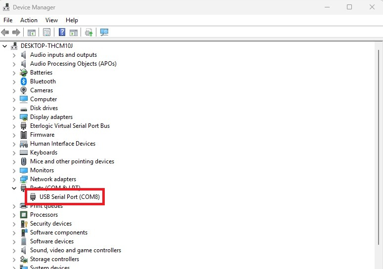
Check your device manager to find the COM port assigned to the connection.
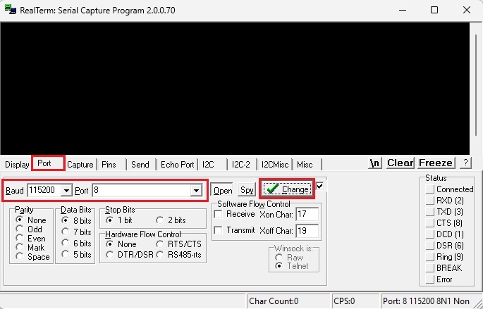
Open RealTerm and go to Port tab. Set Baud to default 115200 (or whatever serial baud rate you previously configured) and COM Port to the number you found on the previous step. Press the Change button.
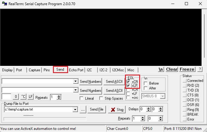
Go to Send tab and activate the EOL +CR +LF checkboxes.
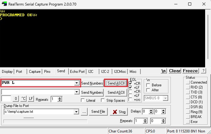
Now you are ready to start sending configuration commands to the radio module. All commands are sent via the UART interface at the configured serial baud rate (115200 bps by default), terminated with a CR+LF (\r\n) end of line.
Commands are space-separated from their parameters. A successful write returns PROGRAMMED OK and sending a command without parameters queries the current value.
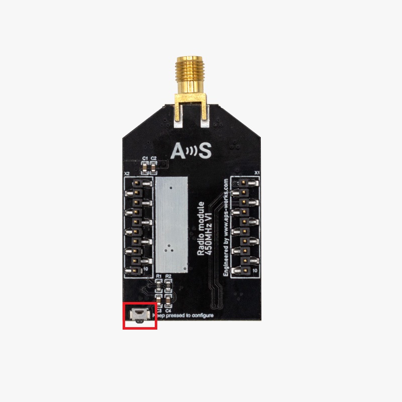
Hold the CONFIG button before sending any command, and release it to return to data transmission mode.
Power
Sets the power level:
H: 30 dBm (1 W) — High power mode (check local regulations before using it).
M: Normal power mode.
L: 27 dBm — Low power (default).
Command
Example
Response
PWR H M L
PWR L
PROGRAMMED OK
PWR (query)
PWR
PWR L
Protocol
Sets the over-the-air protocol. Both ends of the link must use the same protocol and matching air baud rate:
TRIMTALK — 9600 bps only.
TRIMMK3 — 19200 bps only (default).
TRANSEOT— 4800 or 9600 bps.
Command
Example
Response
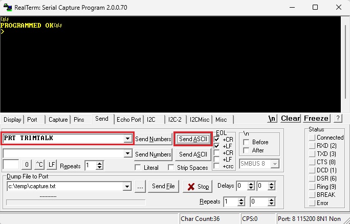
PRT TRIMTALK TRIMMK3 TRANSEOT
PRT TRIMMK3
PROGRAMMED OK
PRT (query)
PRT
PRT TRIMMK3
When using TRANSEOT protocol at 4800 bps data rate is reduced, and therefore you can only send correction data for 2 constellations of satellites.
Air Baud Rate
Sets the over-the-air baud rate. Must match the protocol in use — see protocol table above. Default is 19200 bps.
Command
Example
Response
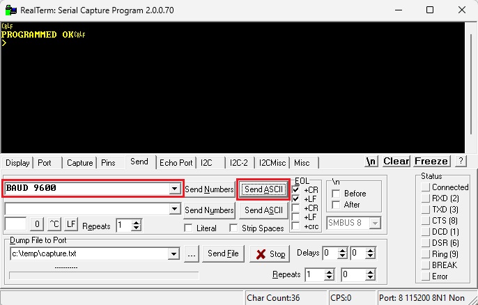
BAUD 4800 9600 19200
BAUD 19200
PROGRAMMED OK
BAUD (query)
BAUD
BAUD 19200
Serial Baud Rate
Sets the UART baud rate between the module and the host. Default is 115200 bps. If you change this, reconnect your terminal at the new rate before sending further commands.
Command
Example
Response
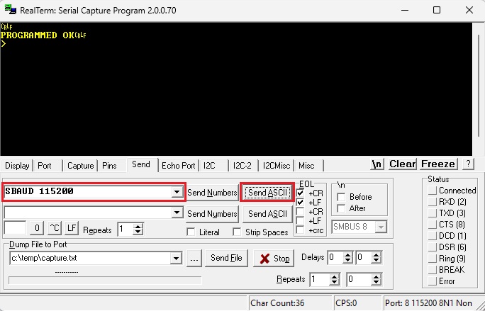
SBAUD 9600 19200 38400 57600 115200
SBAUD 115200
PROGRAMMED OK
SBAUD (query)
SBAUD
SBAUD 115200
Hardware
Pinout
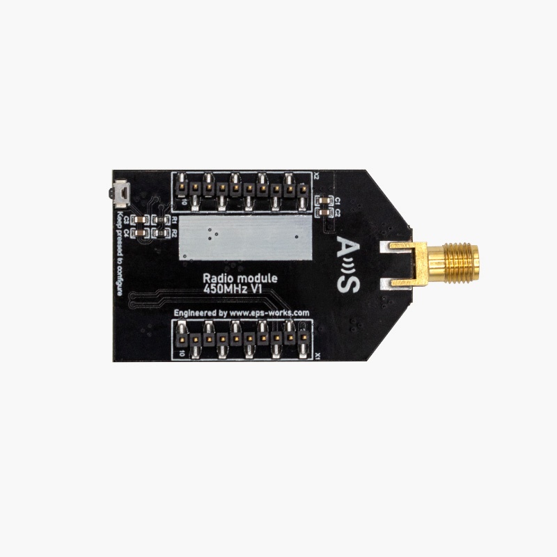
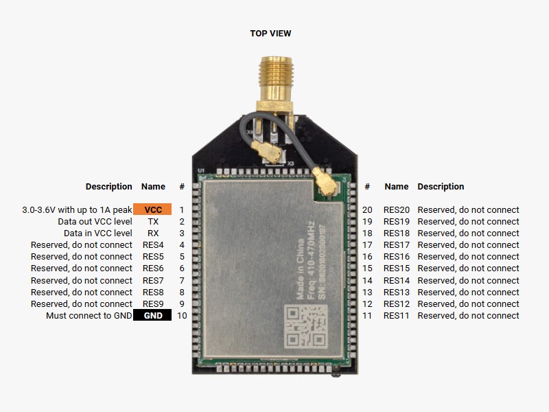
The Radio Module 450MHz uses the standard XBee 2mm pitch 20-pin footprint. Only VCC, TX, RX and GND are connected — all others are reserved and must not be connected.
Pin 1 – VCC: Power supply 3.3–3.6 V. Must be connected.
Pin 2 – TX: Serial data out (3.3 V logic). Connect to host RX.
Pin 3 – RX: Serial data in (3.3 V logic). Connect to host TX.
Pin 10 – GND: Ground. Must be connected.
Pin 4 to 9 and 11 to 20: Reserved. Do not connect.
Antenna
The Radio Module 450MHz requires a good quality dipole antenna, if you use a generic dipole antenna you will not achieve the expected performance. The antenna has to be specific for the 450 MHz frequency, as the ArduSimple Dipole antenna for 450MHz radio.
Always connect the antenna before powering the board to avoid overheating, specially if configured at the maximum output power of 1 Watt. That being said, just connect the antenna to the SMA connector without using tools (the strength of your fingers is enough).
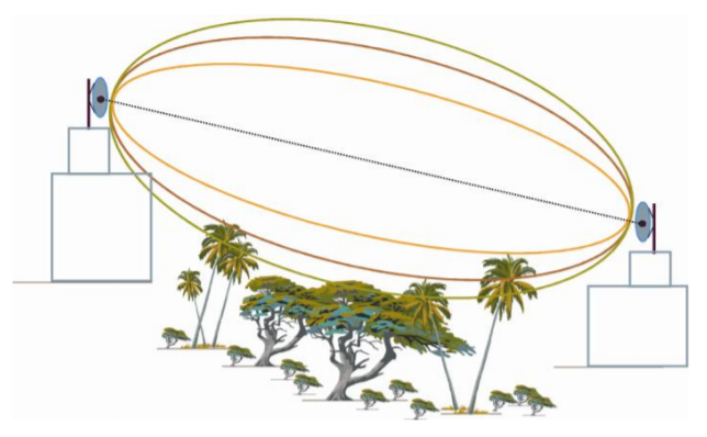
The placement of the antennas is also key to achieve best results. The antennas on both emitter and receivers should have diret line of sight to each other, without any obstructing objects (buildings, trees, laptop screen, …) in-between them. Also as much separation from the ground as possible is recommended for best performance. Please check our tutorial on Visual vs. RF Line-of-Sight – What is the difference?
Buttons
Holding the CONFIG button on the PCB puts the module into configuration mode, allowing the user to send commands, and releasing it returns to data transmission mode.
See the Configuration section to find the commands.


 and
and  How to get a quotation