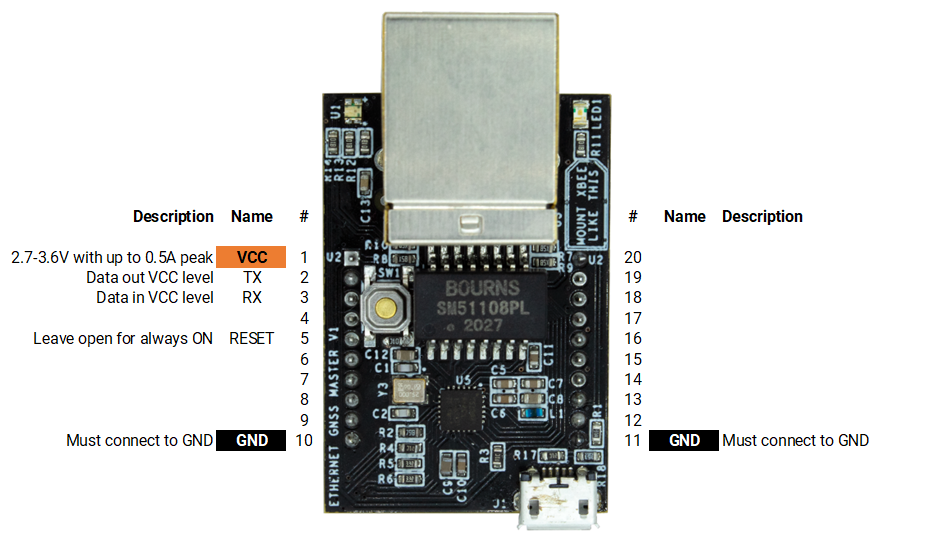
Update (28/03/2024): We have plenty of stock of all our products, find us also in and    Shop now

PCB Integration Guide - Ethernet NTRIP Master

Product briefing:

This product uses a very popular footprint: 2 rows of 10 pins each with a pitch of 2mm between pins. You can integrate this product into your PCB in 2 ways:

  1. Installing receptacles on your PCB so you can connect and disconnect the board at your wish. This option is more flexible but is not very rugged for vibrating environments. Another recommendation that we can give you is to not use cheap receptacles. Cheap receptacles (especially popular from unknown chinese suppliers) use very contaminated  metals for the contacts, which leads to sporadic failures in the field and early death of the socket. We can recommend the top quality Samtec MMS-110-01-L-SV.
  2. Soldering directly to your PCB. This is the most robust way to use this product to avoid reliability issues in the field. And because of the through hole footprint, if another component in your PCB design fails, with a bit of skills you can still recover this expensive component. Or if you decide to make a new PCB design you can always remove from old PCB this component and mount it in the new one.

Either way you will need the footprint dimensions. As there are tons of different softwares for PCB design, we decided to use a 3rd party service to generate a footprint compatible with all possible softwares. You will have to register but then you will have access to thousands of footprints.

Pinout:

The following diagram shows the different pins available including its functionality.

PCB Footprint:

As there are so many softwares, we used an external company to develop footprint libraries for all possible software. You can download them from this link. If you face any problem just contact us.

3D model:

You can download the STEP model from this page.

Integration considerations

The board itself is quite immune to noise and doesn’t generate excessive noise itself. Nevertheless we recommend to follow these guidelines:

  • If you have a digital area and an analog area, place it in the digital area.
  • If you have a high voltage and a low voltage area, place it in the low voltage area.
  • GPS signals are extremely weak. Place any GPS antenna in your system as far away as possible.

Configuration and Software Integration

You will find this information in our Hookup Guides.

Want to learn more about GPS/RTK?

1. Our engineering team will contact you to solve any questions
2. We will keep you updated about promotions and new product releases
3.You will only hear from us when we have important news, we won’t spam your email