 and
and 
PCB Integration Guide - 4G NTRIP Master
Product briefing:
This product uses a very popular footprint: 2 rows of 10 pins each with a pitch of 2mm between pins. You can integrate this product into your PCB in 2 ways:
- Installing receptacles on your PCB so you can connect and disconnect the board at your wish. This option is more flexible but is not very rugged for vibrating environments. Another recommendation that we can give you is to not use cheap receptacles. Cheap receptacles (especially popular from unknown chinese suppliers) use very contaminated metals for the contacts, which leads to sporadic failures in the field and early death of the socket. We can recommend the top quality Samtec MMS-110-01-L-SV.
- Soldering directly to your PCB. This is the most robust way to use this product to avoid reliability issues in the field. And because of the through hole footprint, if another component in your PCB design fails, with a bit of skills you can still recover this expensive component. Or if you decide to make a new PCB design you can always remove from old PCB this component and mount it in the new one.
Either way you will need the footprint dimensions. As there are tons of different softwares for PCB design, we decided to use a 3rd party service to generate a footprint compatible with all possible softwares. You will have to register but then you will have access to thousands of footprints.
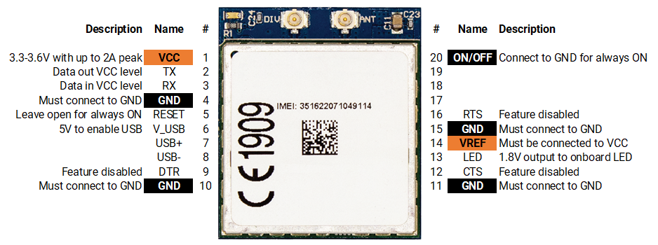
Pinout:
The following diagram shows the different pins available including its functionality.
PCB Footprint:
As there are so many softwares, we used an external company to develop footprint libraries for all possible software. You can download them from this link. If you face any problem just contact us.
Integration considerations
Due to high power requirements, this product can introduce some noise in the power supply line. If you don’t have much RF expertise, it is easier to simply use a dedicated power supply regulator for this module. You can use either a LDO or a DC/DC converter to power this board:
- LDO. This option is easier to design because usually you don’t need to many external components and everything is inside a basic package with not too many pins. The disadvantage is that it’s not very powr efficient and it will get hotter. The only requirement is that it can provide 2A constant current, although will be used at 20% of it’s power capacity most of the time.
- DC/DC. This option gives more work to the designer and to source components, because usually it’s in small packages with a lot of pins and it requires a few external components to run. The advantage is that it’s very efficient and the system will not get hot and will require less current from your battery pack / power source. Requirement is that it can provide 2A constant current and that the switching frequency is minimum 500kHz.
The board itself is quite immune to other noises, but the 4G/3G/2G antennas are very sensitive to noise and transmit with a lot of power so they can make RF noise. Therefore it is recommended to place the 4G/3G/2G antennas:
- As far away as possible from any analog / RF electronics.
- As far away as possible from your GPS antennas or any other RF antenna
Configuration and Software Integration
You will find this information in our Hookup Guides.
-
Sale!
 Plugins
4G NTRIP Master
156,00€ Select options This product has multiple variants. The options may be chosen on the product page