Update (30/08/2025): We have plenty of stock of all our products, find us also in and    Shop now

How to calculate the volume of soil or gravel to check the contactor’s quotation
step by step manual how to calculate volume using low cost rtk kit and free software

In construction and earthworks projects, one of the most common questions is: how much soil or gravel has really been moved? Contractors often provide volume estimates in their quotations, but as the project owner it’s important to verify these numbers with accurate measurements.

In this tutorial, we’ll show you step by step how to calculate the actual volume of soil or gravel using modern surveying tools: a non-RTK drone, anRTK kit to measure precise Ground Control Points (GCPs), and free software to build a georeferenced 3D model and compute the volume difference between two surveys (before and after the earthworks).

By following this process, you’ll be able to independently check your contractor’s quotation, ensure transparency, and make data-driven decisions. Even if you are new to photogrammetry or RTK surveying, the steps are practical and easy to replicate.

Note: This tutorial does not cover how to place GCPs on the ground, measure their precise coordinates with the RTK Calibrated Surveyor Kit, or capture drone images. These steps are already explained in our tutorial How to create accurate 3D photogrammetry maps using GCPs and a non-RTK drone (Steps 1–40). Please complete those steps first to obtain two image datasets (before and after the earthworks).

Required hardware:

  • a laptop or computer

Required software:

How to measure soil and gravel volume changes during earthworks

Prepare your image data

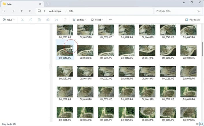
  1. After completing your first survey (before works) and returning to the office, download the photos from your drone’s SD card to your computer. Create a main project folder on your drive, then add a subfolder named foto. Copy all drone images into this folder and ensure they are saved in JPG format.
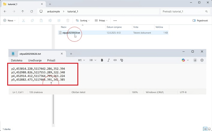
  1. Create another subfolder and save the coordinates of the Ground Control Points (measured with the RTK Calibrated Surveyor Kit) into it. Include at least: Name, X, Y, Z.

Build 3D model in RealityScan

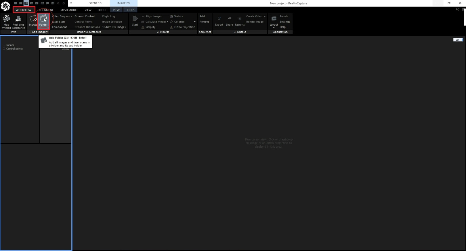
  1. Open RealityCapture. Click Workflow->Folder.
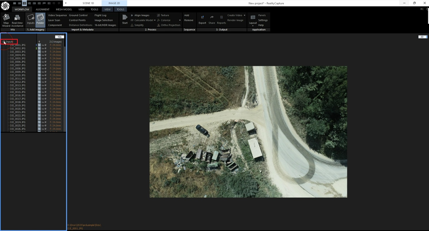
  1. Navigate to your folder with images and press Choose Folder. Wait for images to appear in the 1Ds view and 2D view.
  2. Press + to see photos listed.
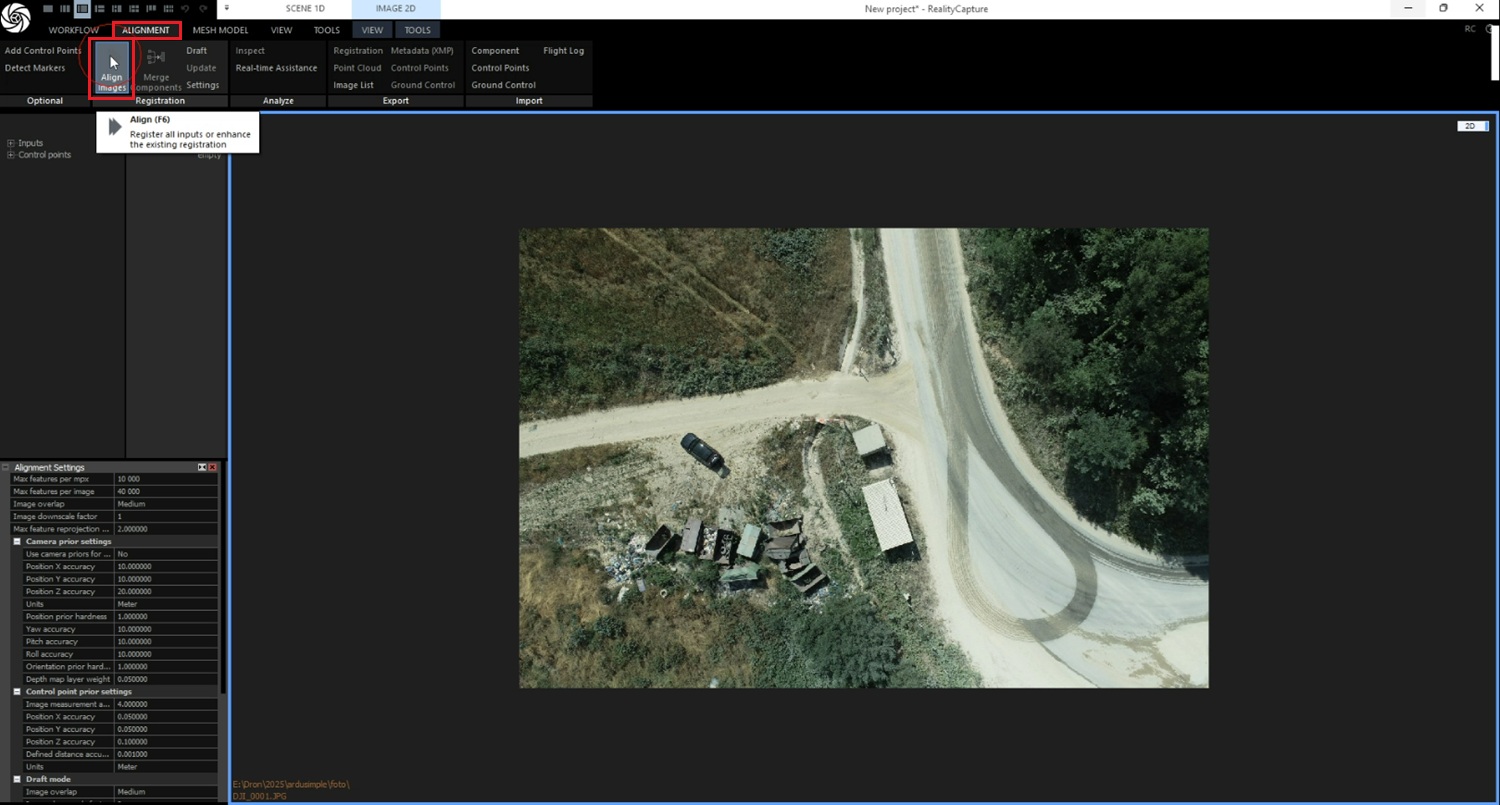
  1. Click Alignment->Align images.
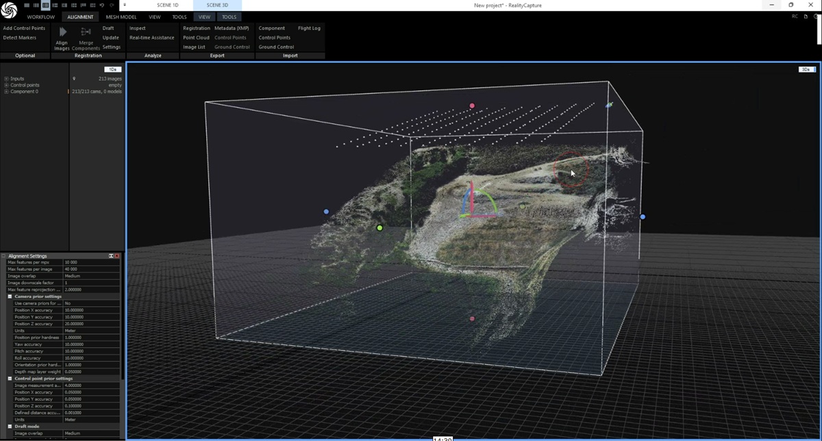
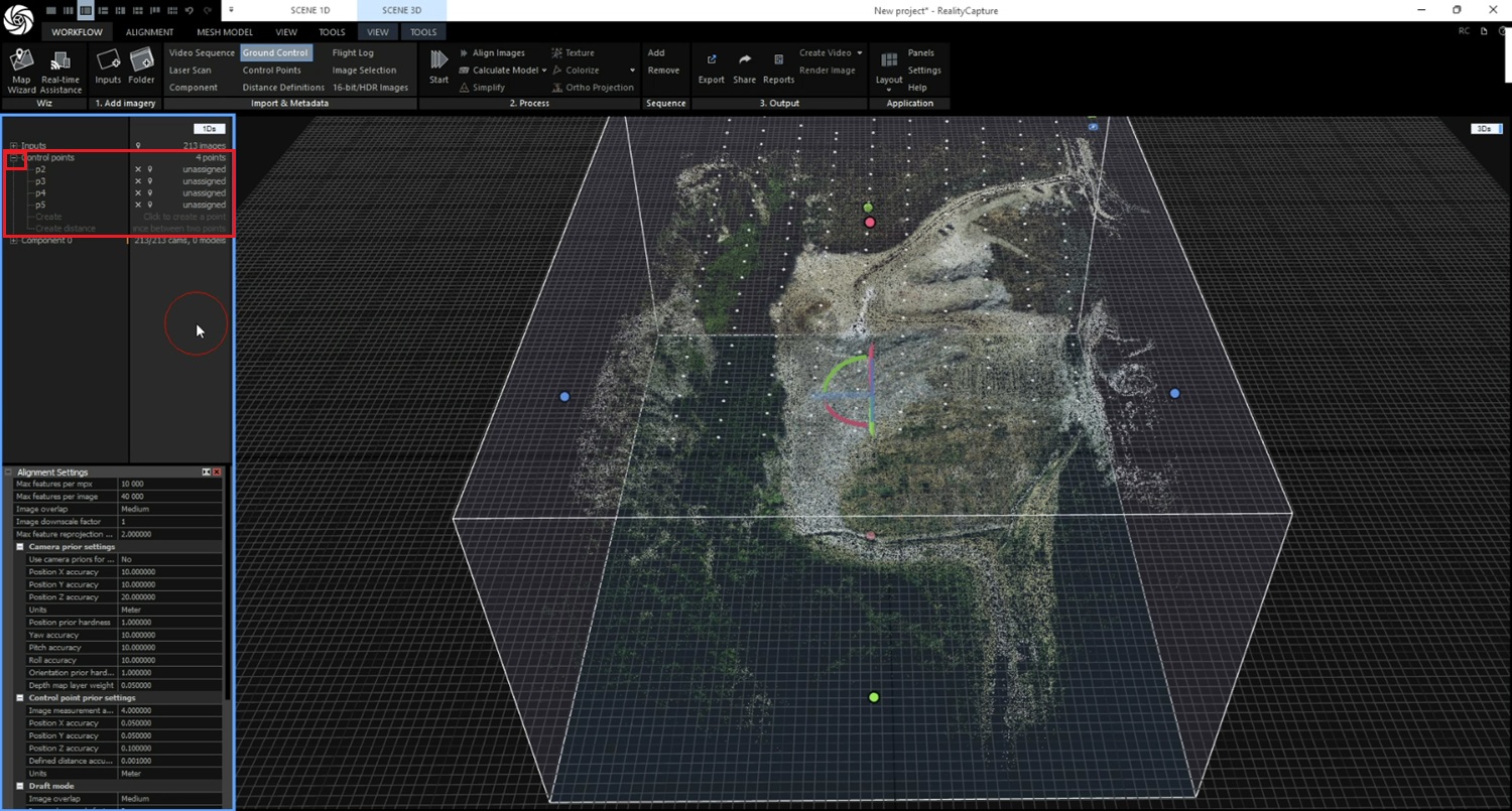
  1. Wait for alignment to complete. Once finished, you will see a sparse point cloud in the 3D view.
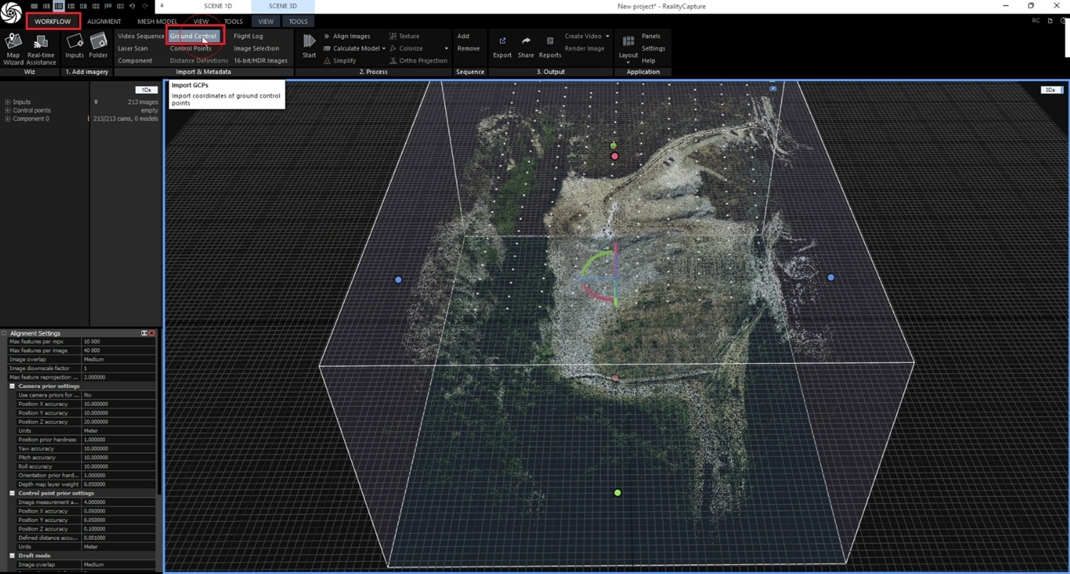
  1. Click Workflow->Ground control.
  1. Select your GCP TXT file and click Open.
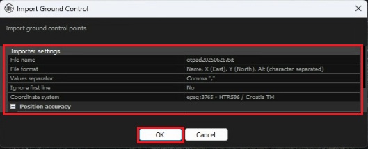
  2. Check import settings (select separator type, GCP Coordinate system (CRS) that matches your survey, confirm horizontal CRS (e.g., EPSG:XXXX) is correct, etc.) and press OK.
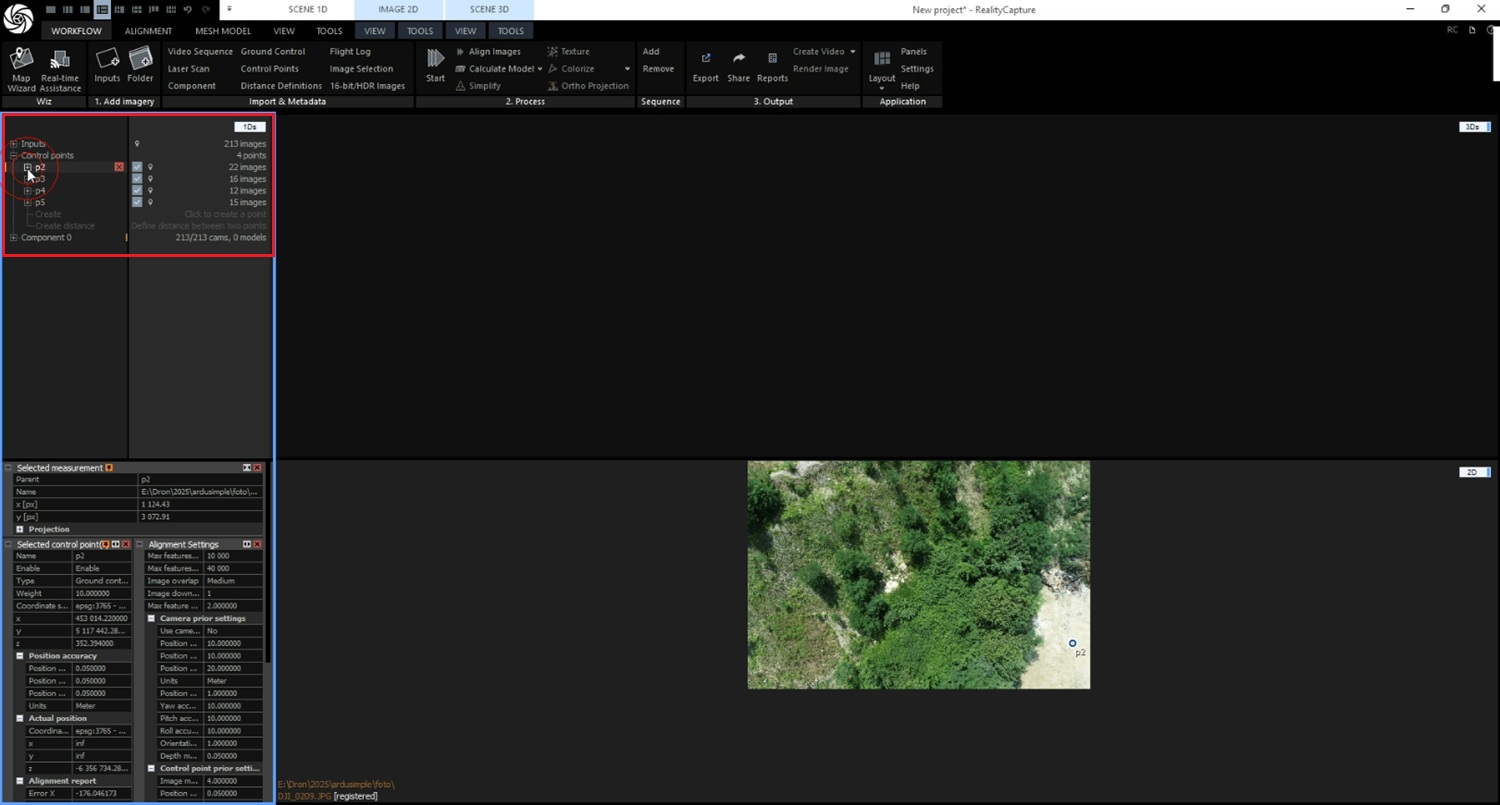
  1. Click + to see Control points are imported.
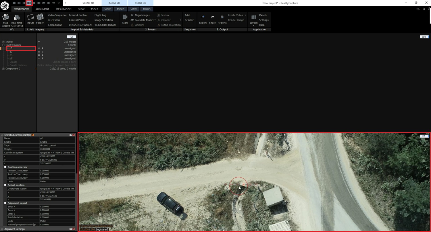
  1. Click on first GCP in 1Ds window and switch to 2D.
  1. Click on 1st GCP and switch to 2D.
  1. Click an image thumbnail where the GCP is visible. Zoom into the target (mouse wheel).
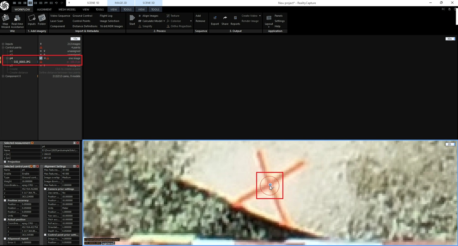
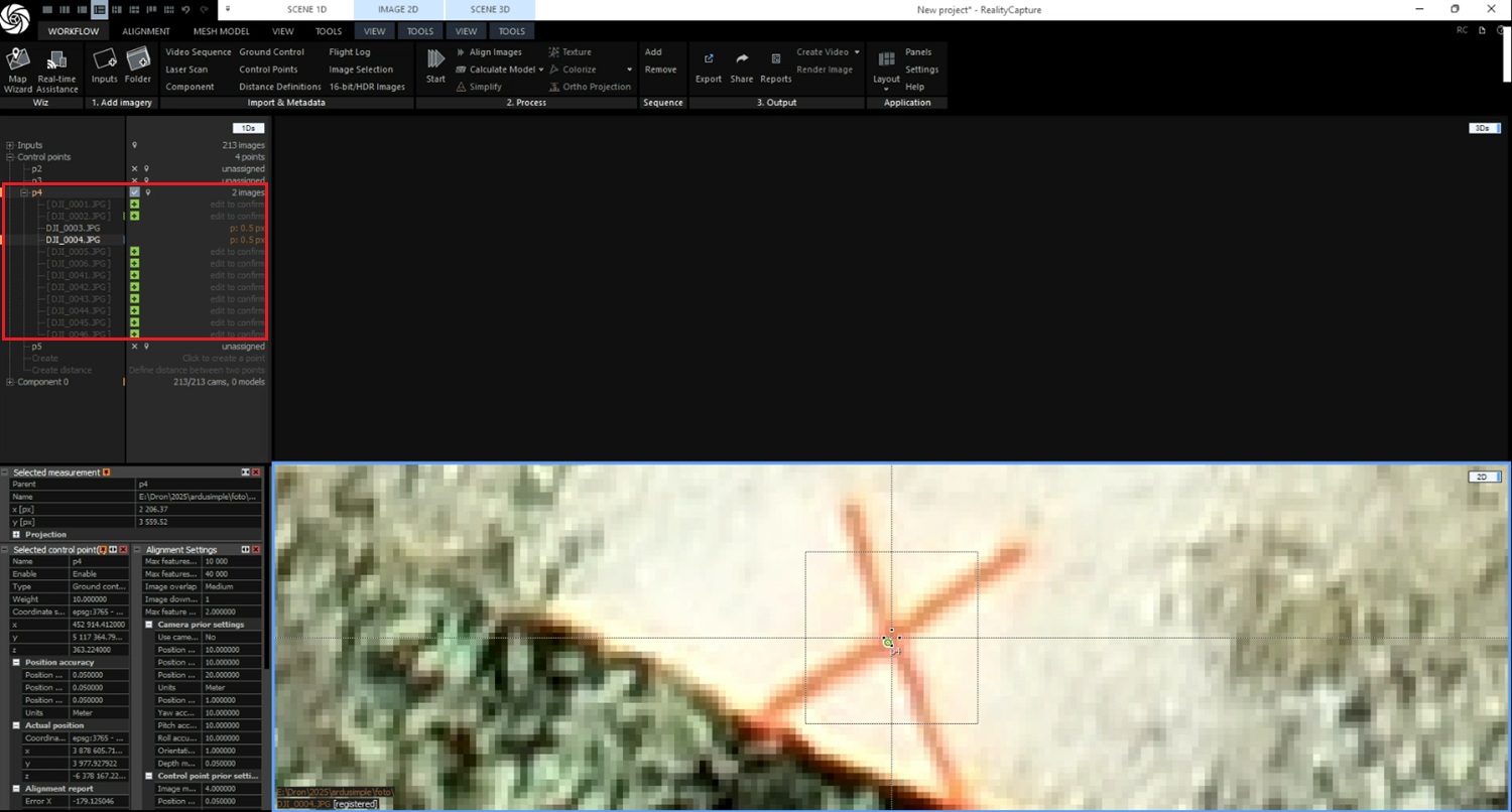
  1. Drag control point and drop it the GCP target center to add a mark.
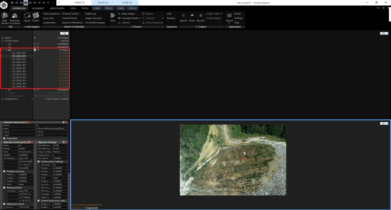
  1. You will see the list of pictures which includes this GCP in 1Ds window.
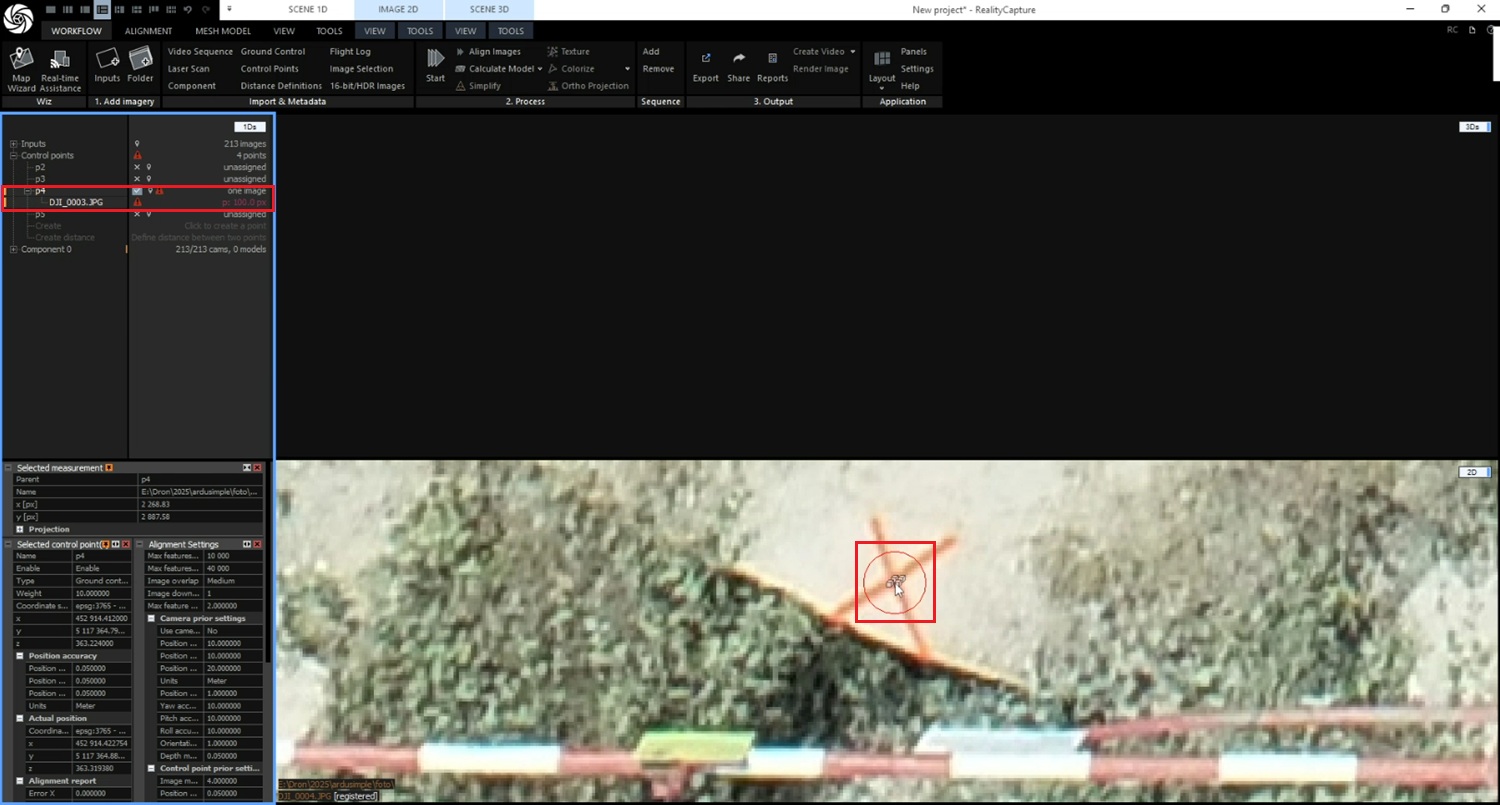
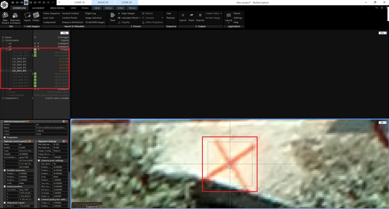
  1. Switch to another image where the same GCP is visible. Adjust a mark to the very GCP target center on each picture.
  1. Once finished with one control point you will see it in 1D view. Ensure each GCP has at least 3 marks on different images.
  1. Move to the next GCP in the list. Repeat marking steps #12-#17 for each remaining GCP.
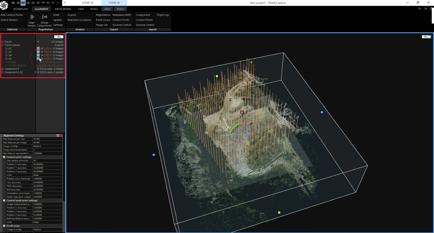
  2. When finished, you will see all marked points in the 1Ds window.
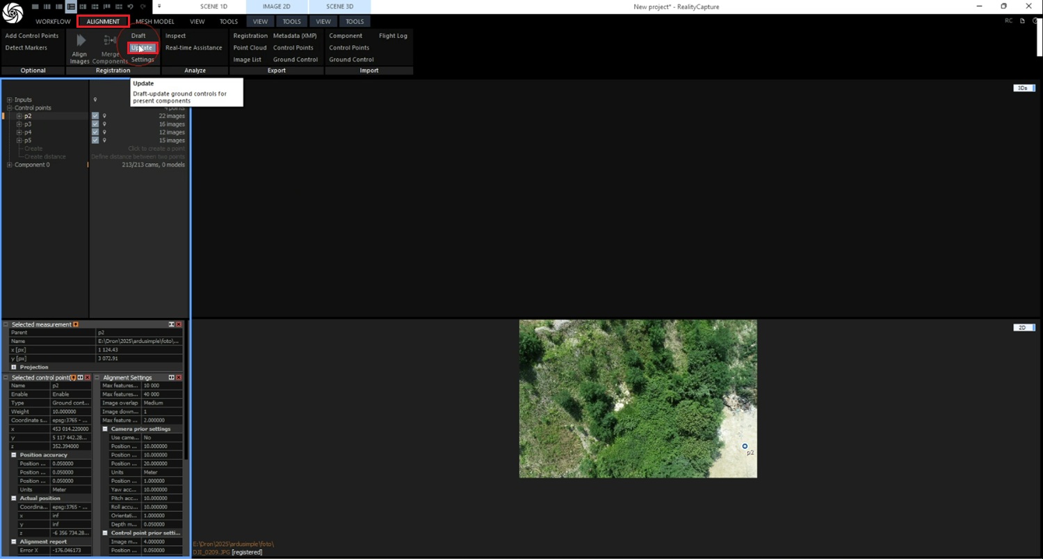
  1. Click Alignment -> Update.
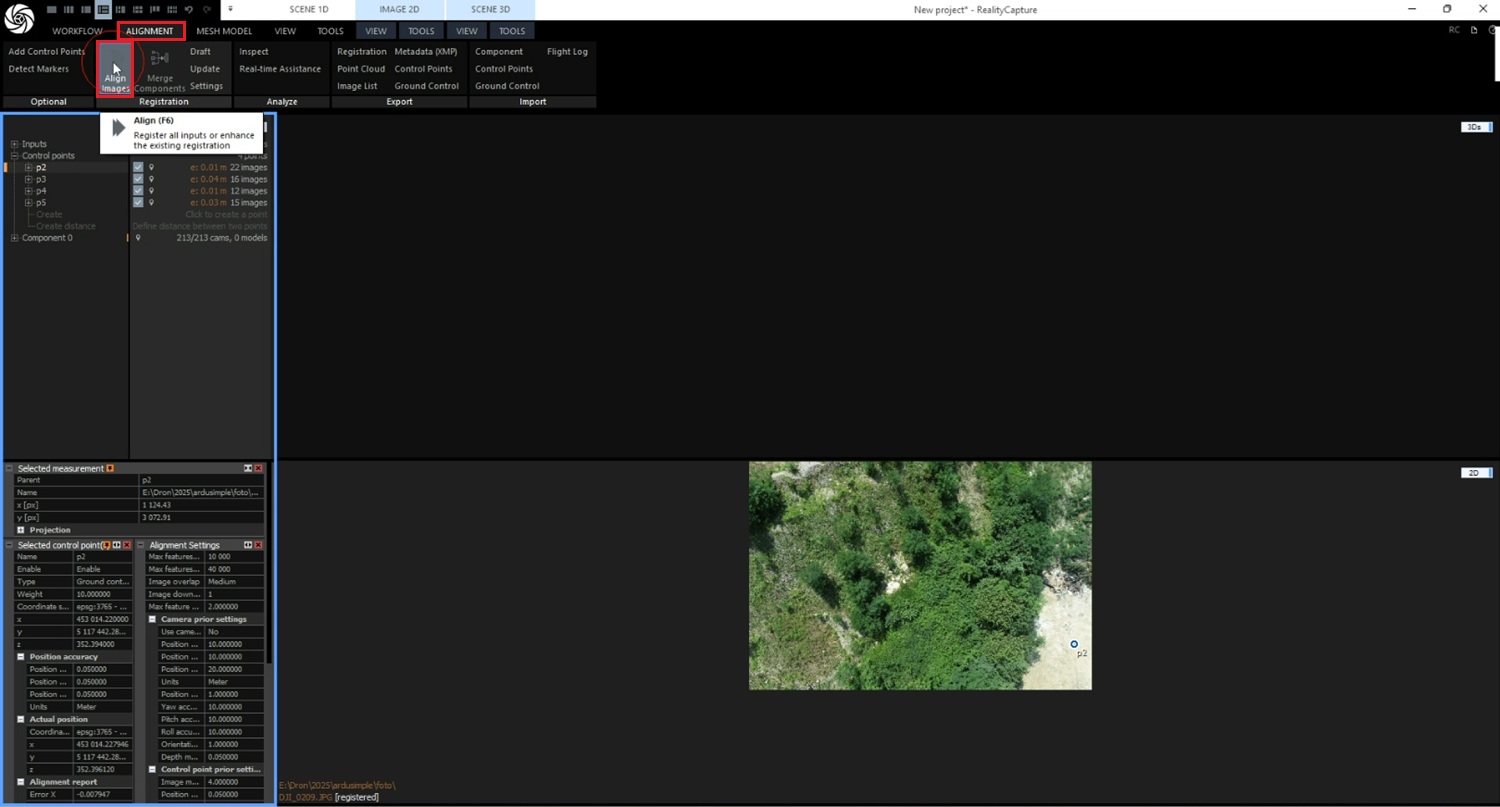
  1. Click Alignment -> Align images.
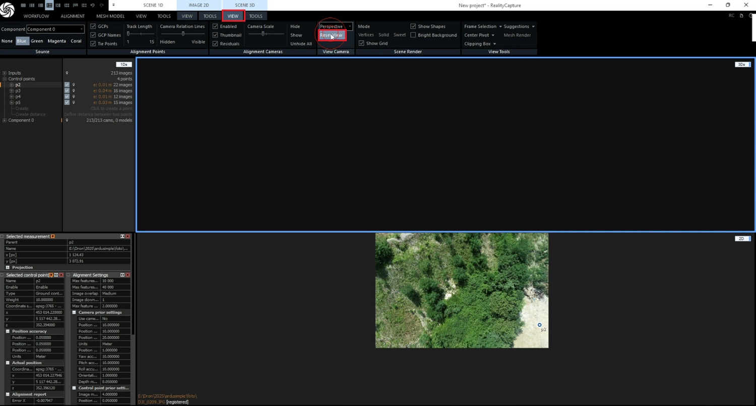
  1. Go to the View->Reset view.
  1. Click Alignment->Update.
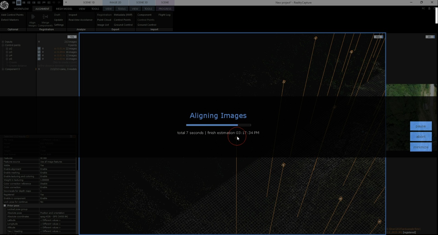
  2. Click Alignment->Align images. Wait for bundle adjustment to finish.
  1. Confirm model is now georeferenced. Confirm residuals decreased to acceptable values (e.g., < 2 cm).
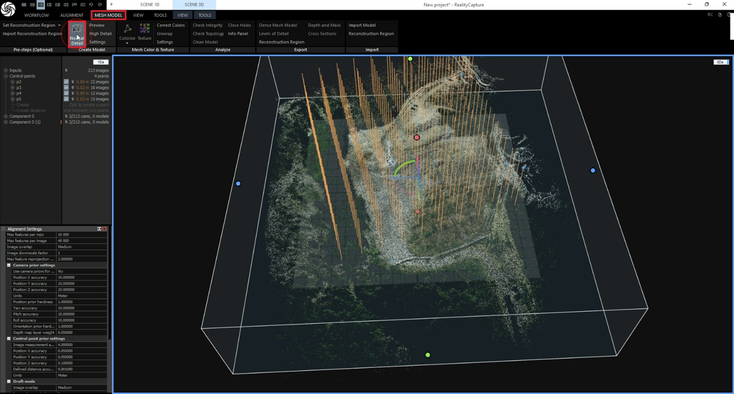
  1. Click Mesh model->Normal detail to generate the mesh. (Optional: select High Detail if you need maximum resolution.)
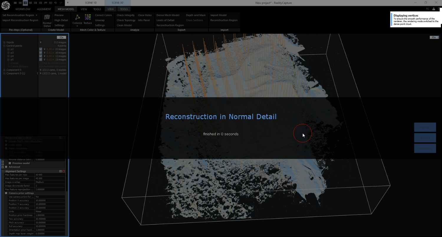
  1. Wait for the Normal Detail reconstruction to complete. In our case, it took about 12 minutes. If you selected High Detail in the previous step, the process will take longer.
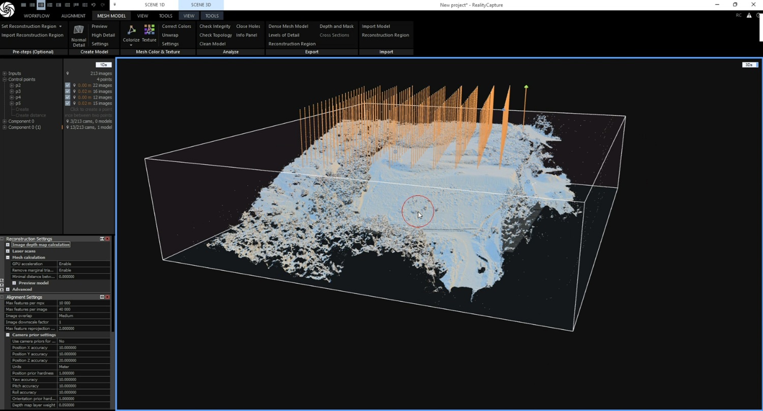
  1. In 3D view, you will see the 3d model in normal detalization. Rotate the box if needed.
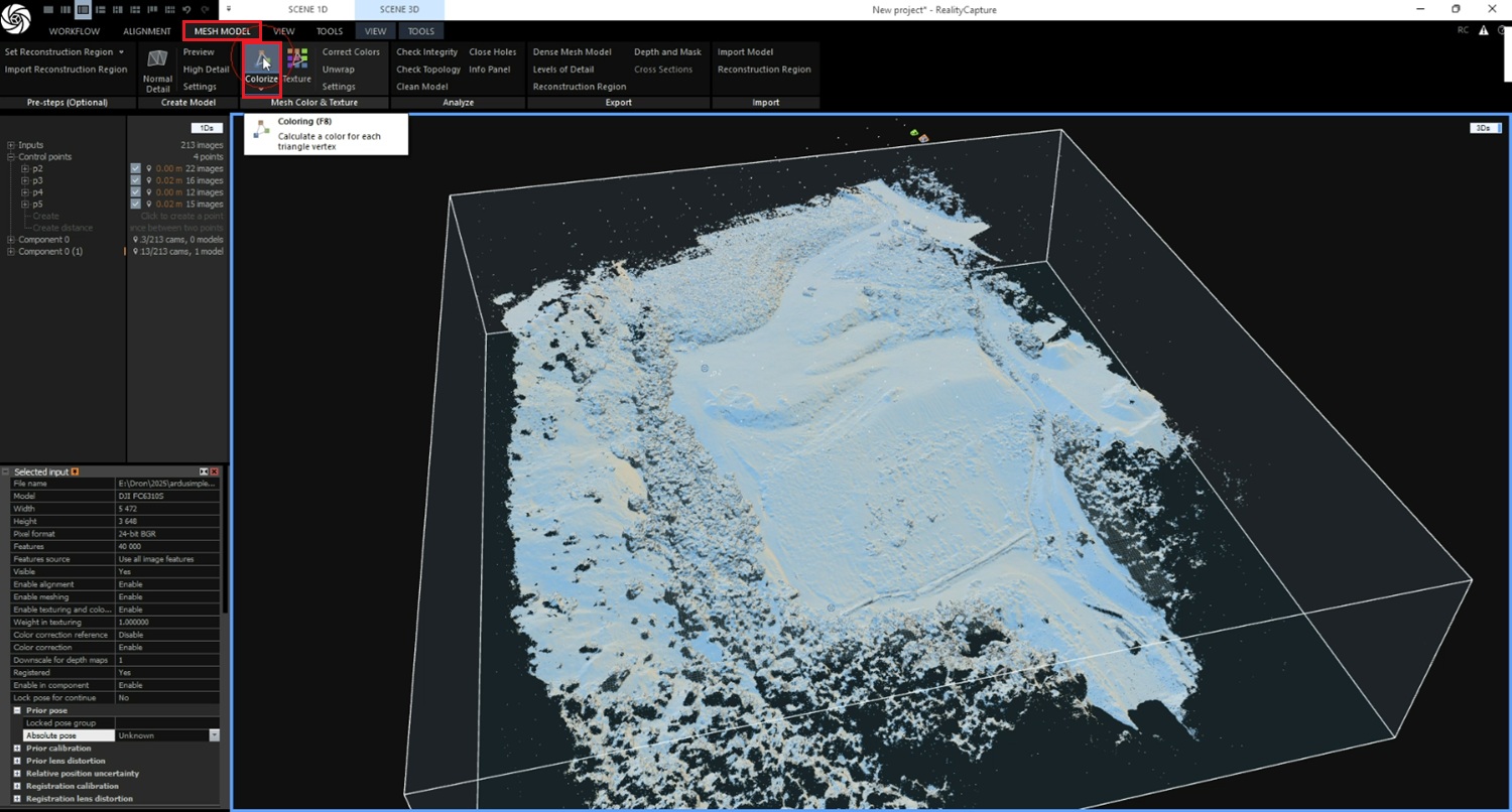
  1. To calculate a color for each triangle vertex, click Mesh model->Colorize.
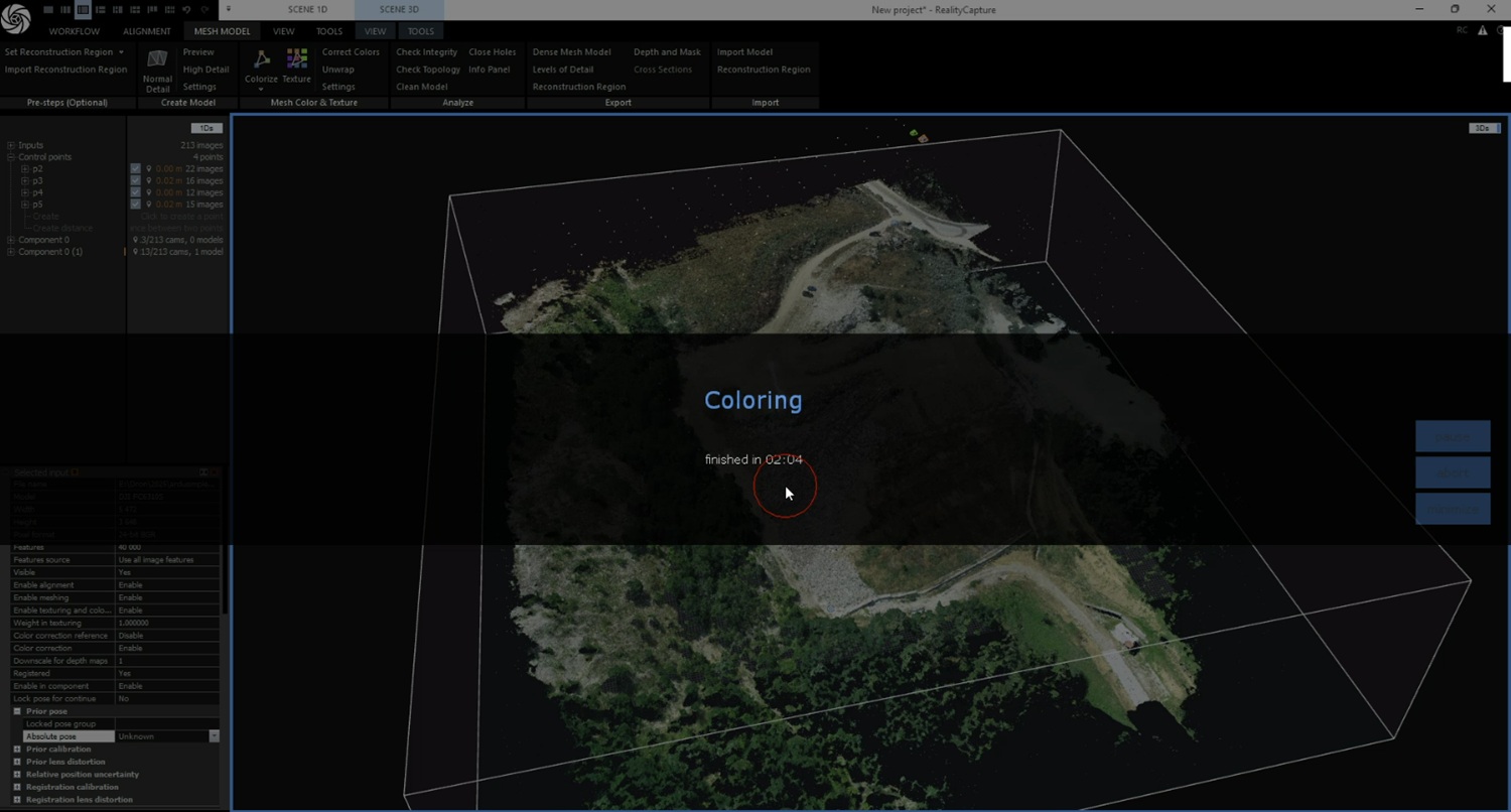
  1. Wait until Coloring finishes. In our case it took 2 minutes. You will see a colored version of your 3d model.
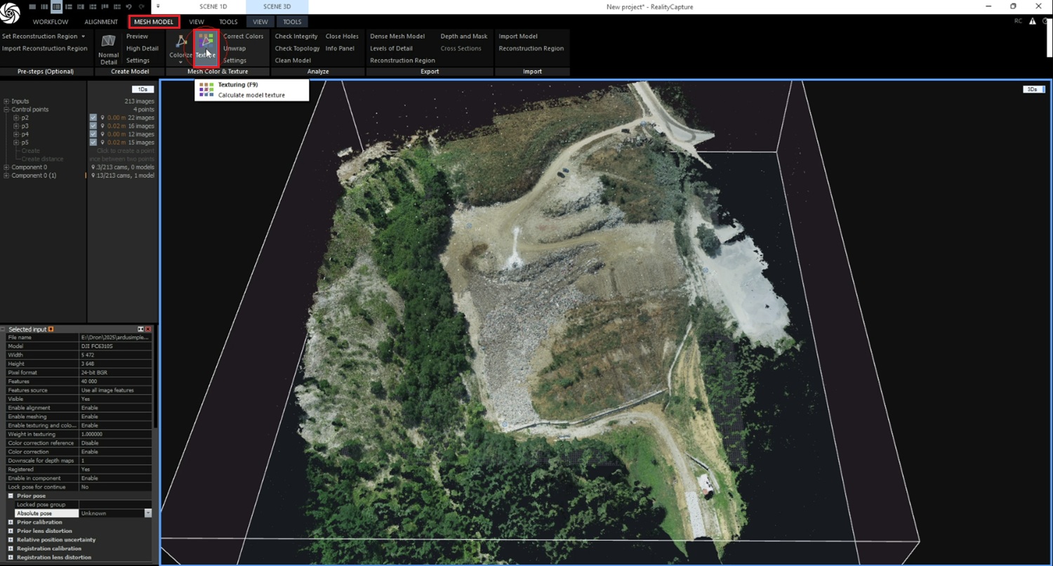
  1. To calculate model texture, click Mesh model->Texture.
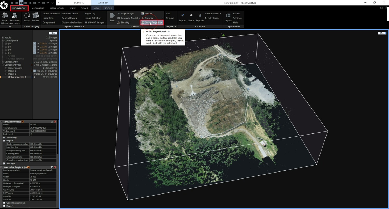
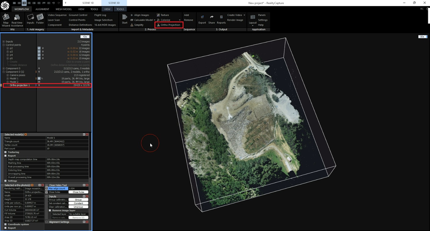
  1. Click Workflow->Ortho projection to create an orthographic projection and a digital surface model of the terrain.
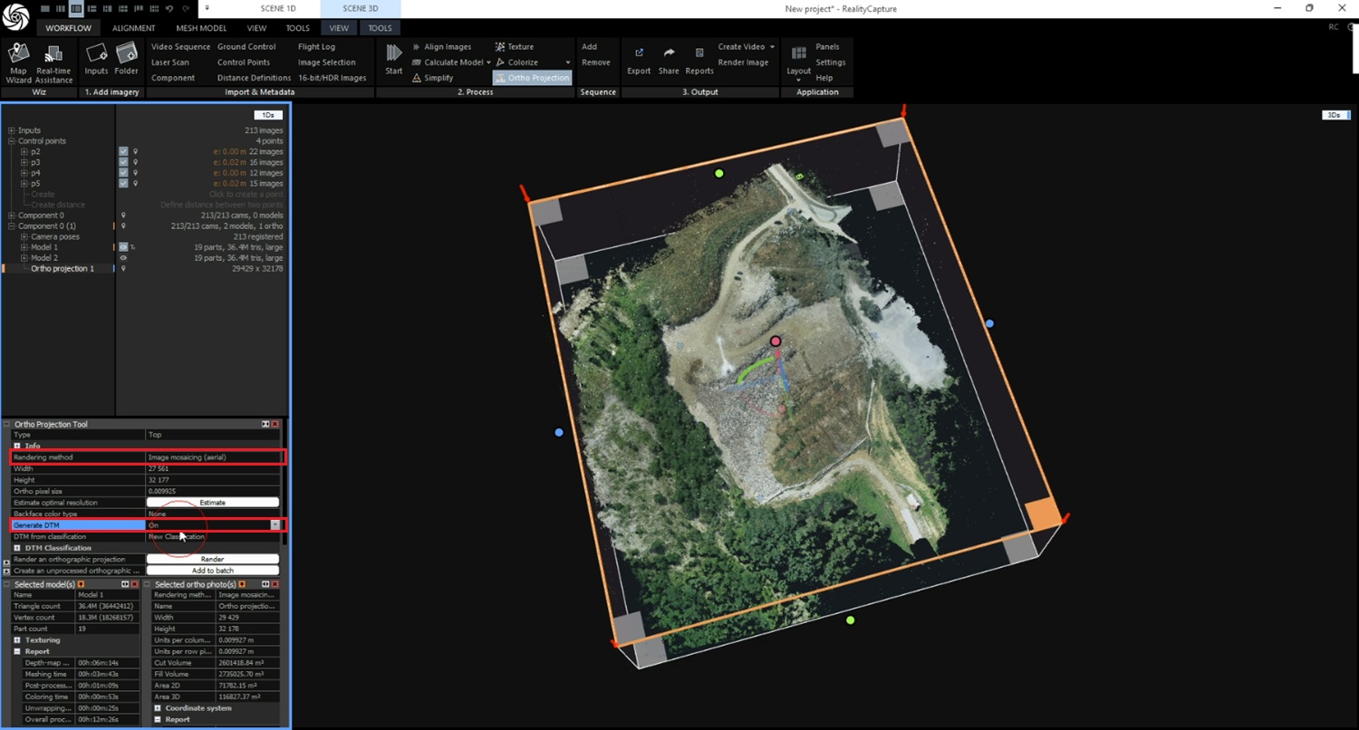
  1. In settings of ortho projection tool, choose Image mosaicing (aerial) on Rendering method. Choose On in Generate DTM.
  1. Click Workflow->Ortho projection. The Ortho projection will appear in 1Ds view.
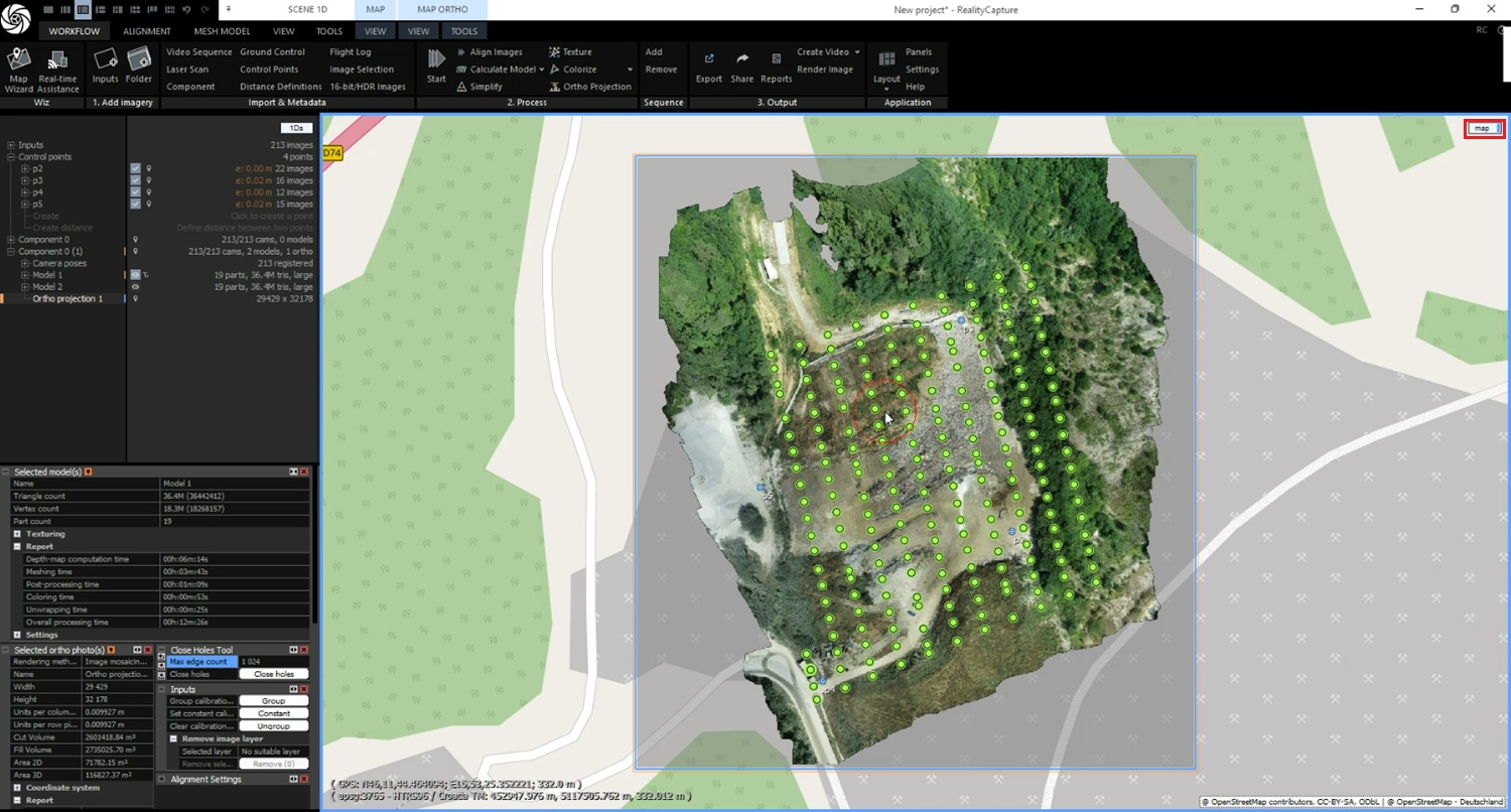
  1. Choose Map view to see your model overlaid on the map.
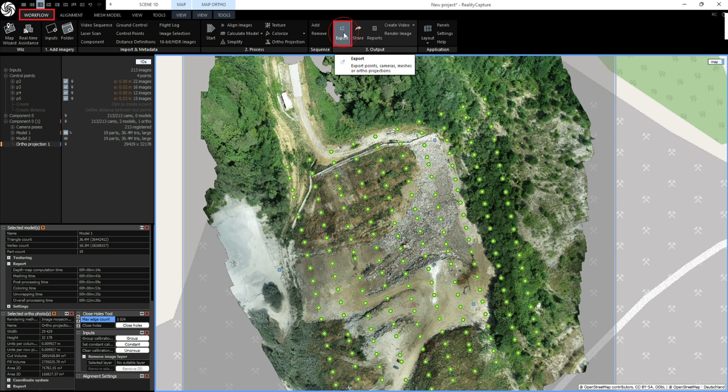
  1. To export the model click Workflow-> Export.
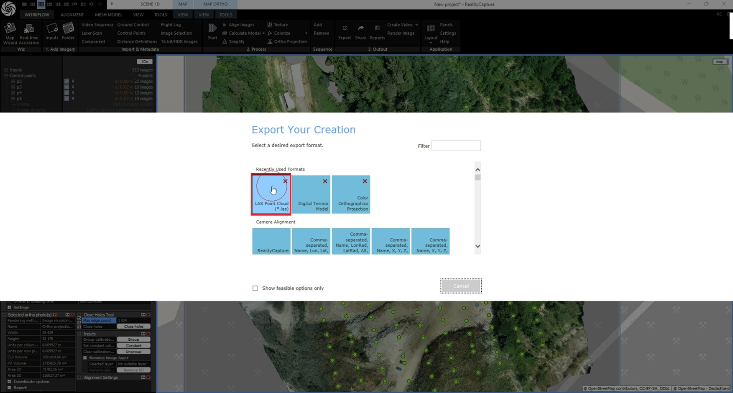
  1. Choose LAS Point Cloud format. Set a filename in your project folder and click Save.
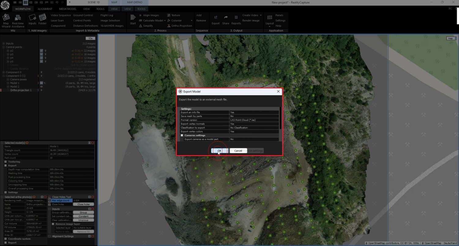
  1. Verify the settings of export and press OK.
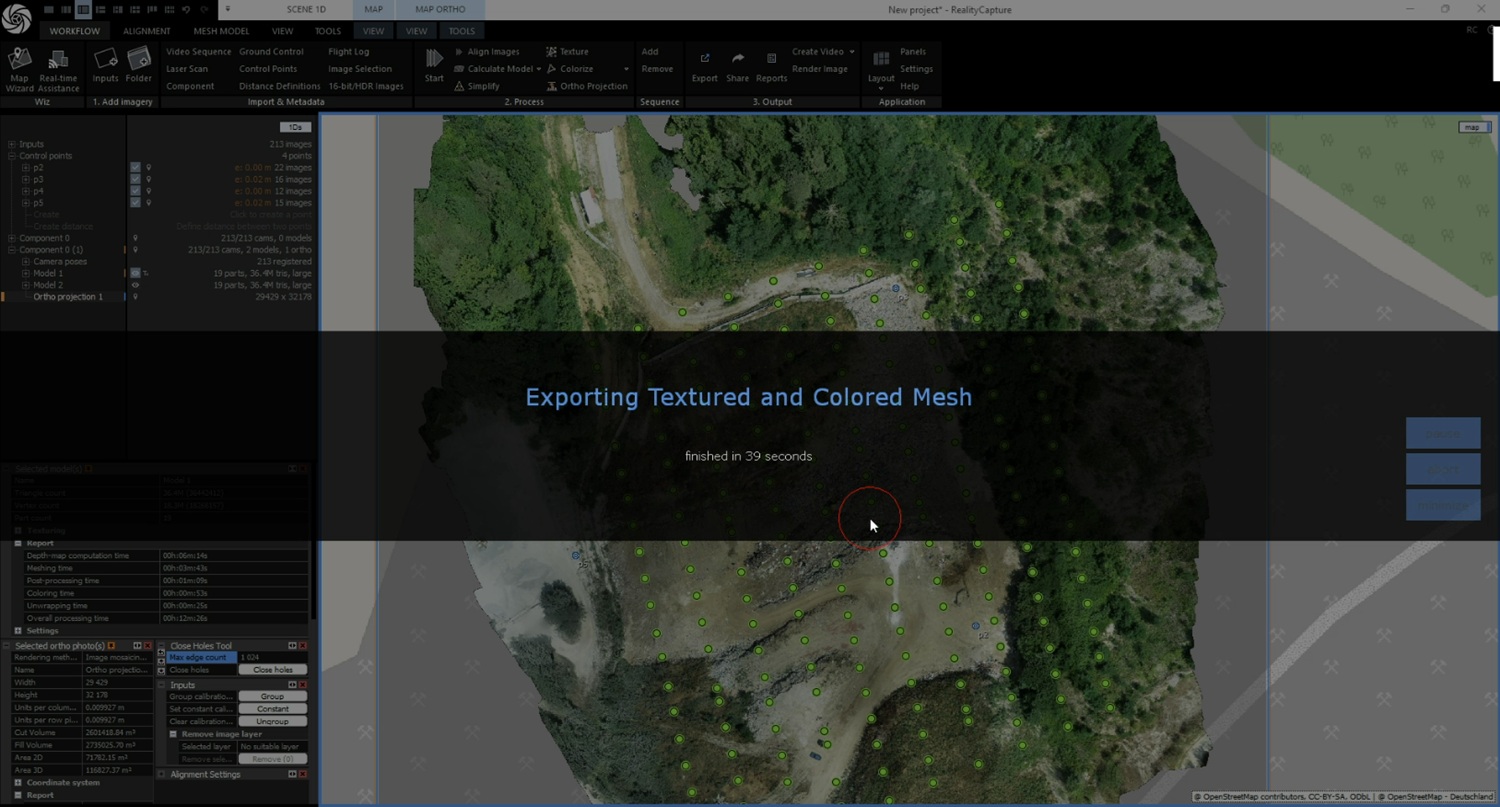
  1. Wait for export to complete.
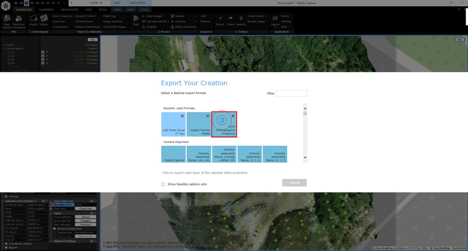
  1. Click Workflow-> Export. Choose Color Orthographics projection format.
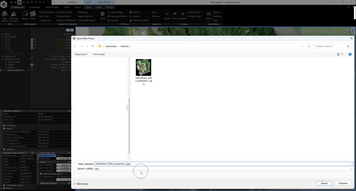
  1. Set a filename in your project folder and click Save.
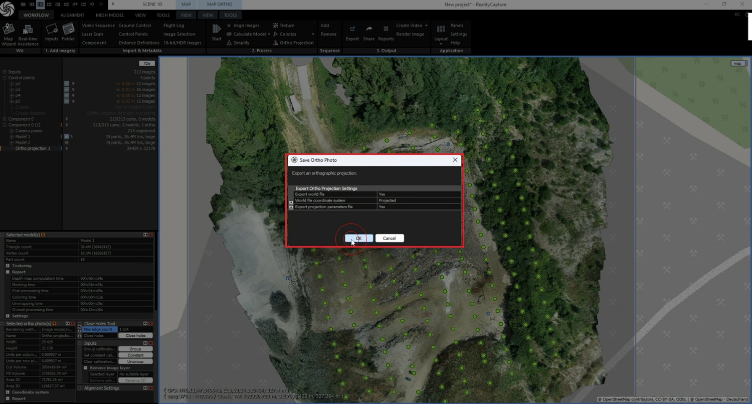
  1. Check setting of export and press Ok.
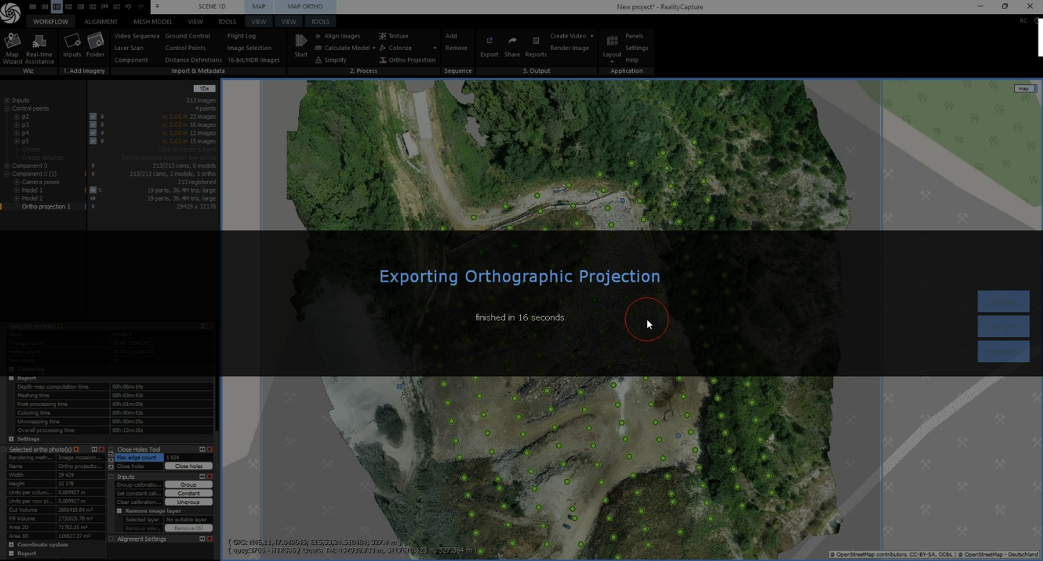
  1. Wait for the export of the orthographic projection to finish. At this point, your initial model is prepared and ready for further analysis.
  1. Next, wait until the contractor has added or removed gravel and you can perform the second drone survey. Then repeat steps 1–43. Once complete, you will have the second model ready for comparison.

Create polyline and segments to define area of interest

The polyline defines the boundary of the area where you want to calculate volume.

    1. Open CloudCompare.
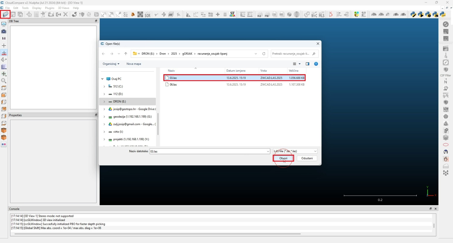
    2. Click Open and load the LAS model that makes it easiest to identify the boundaries of your area of interest (usually the model containing the volume).
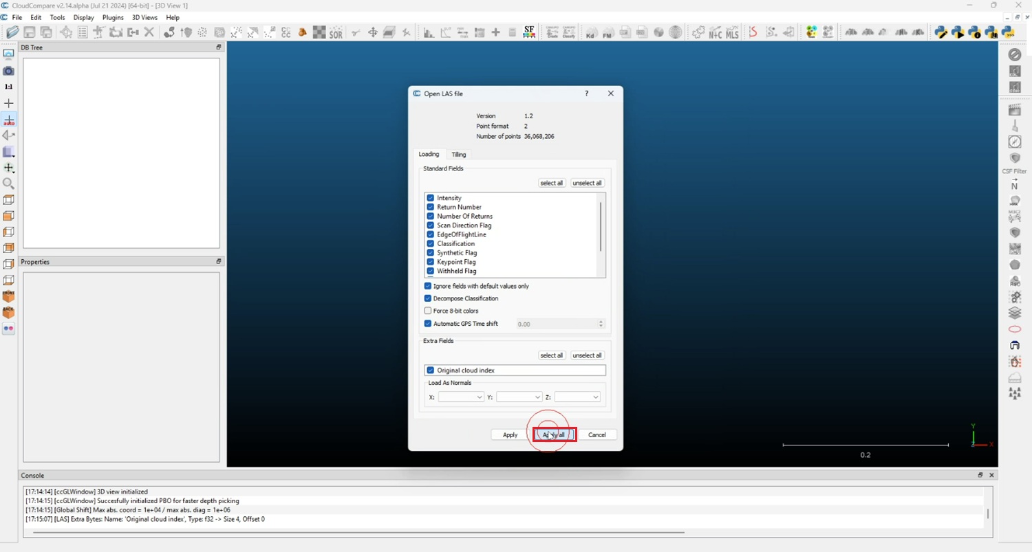
  1. In the dialog, press Apply all.
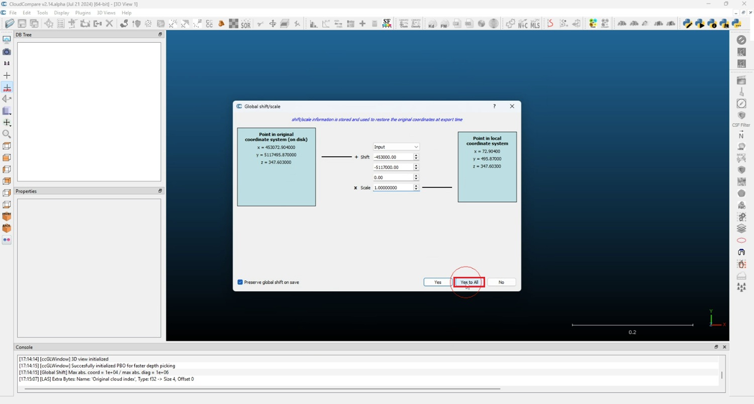
  1. If asked about Global Shift, press Yes to all.
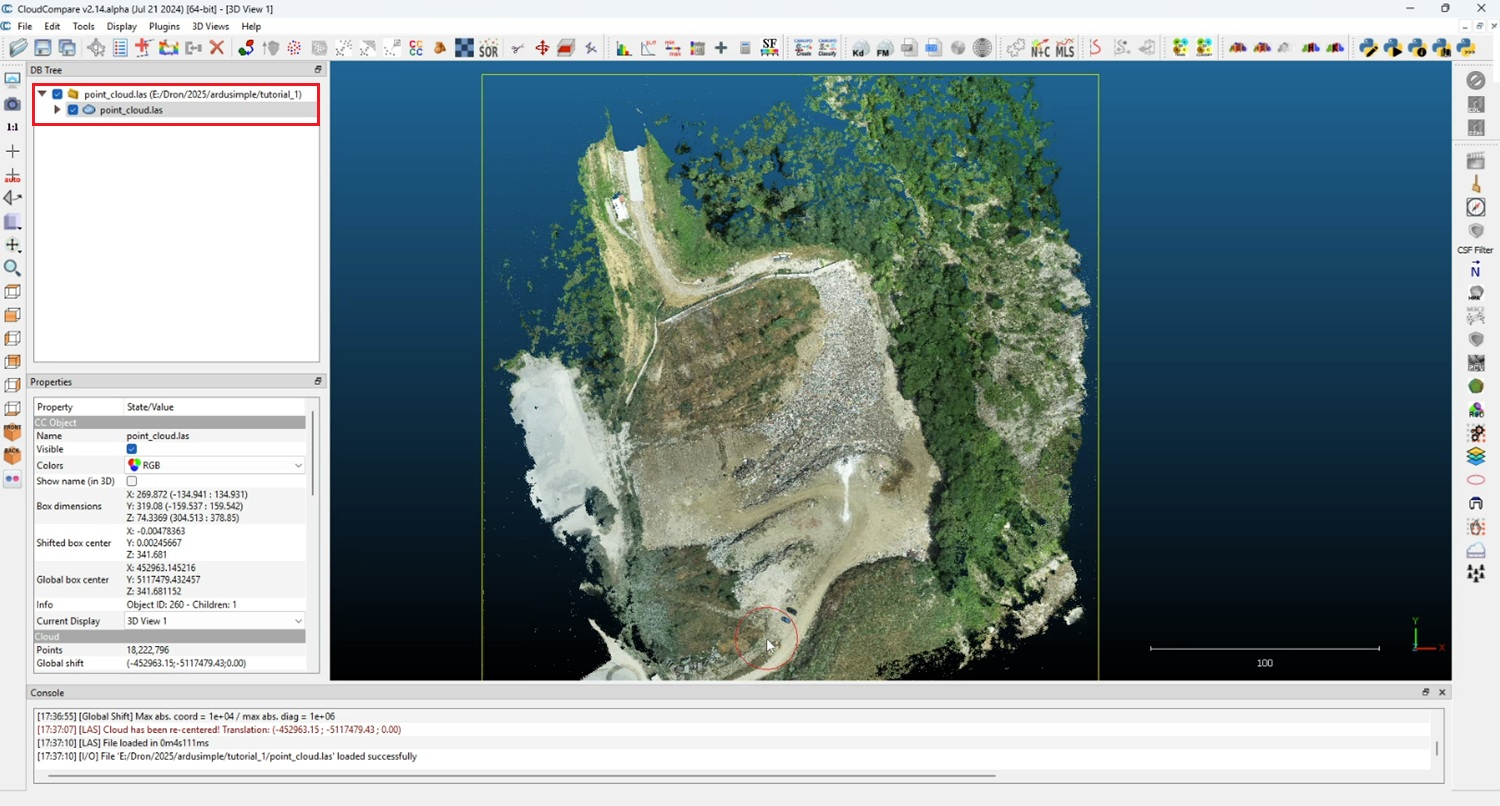
  1. Wait until loading finishes — the 3D model will appear.
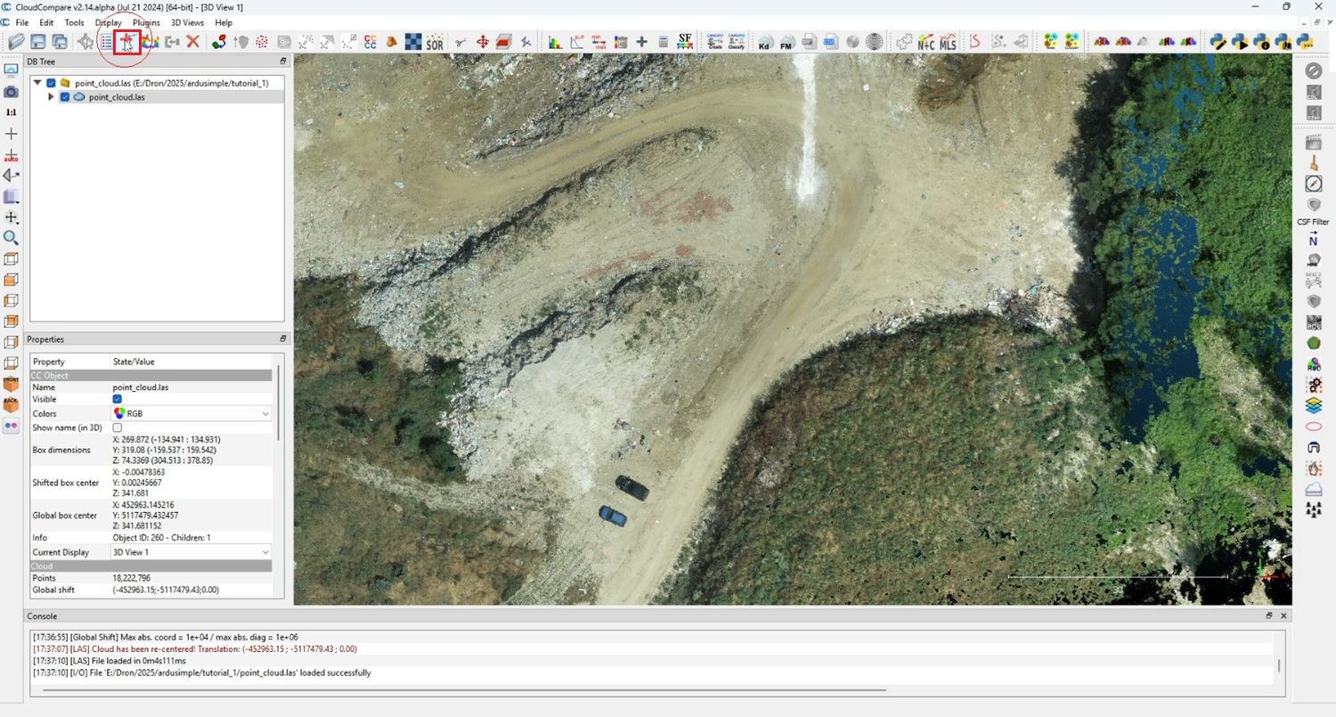
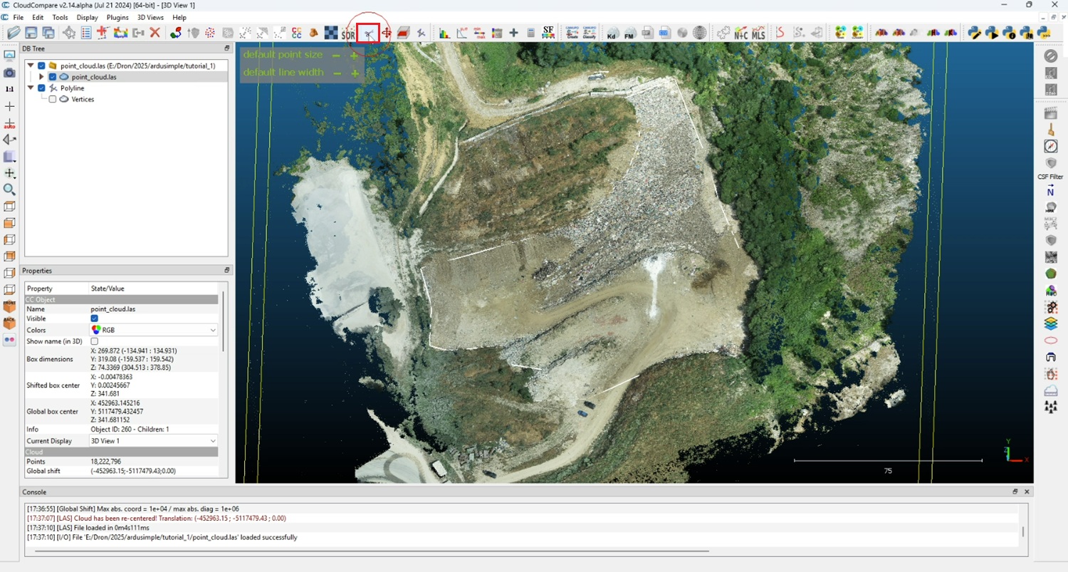
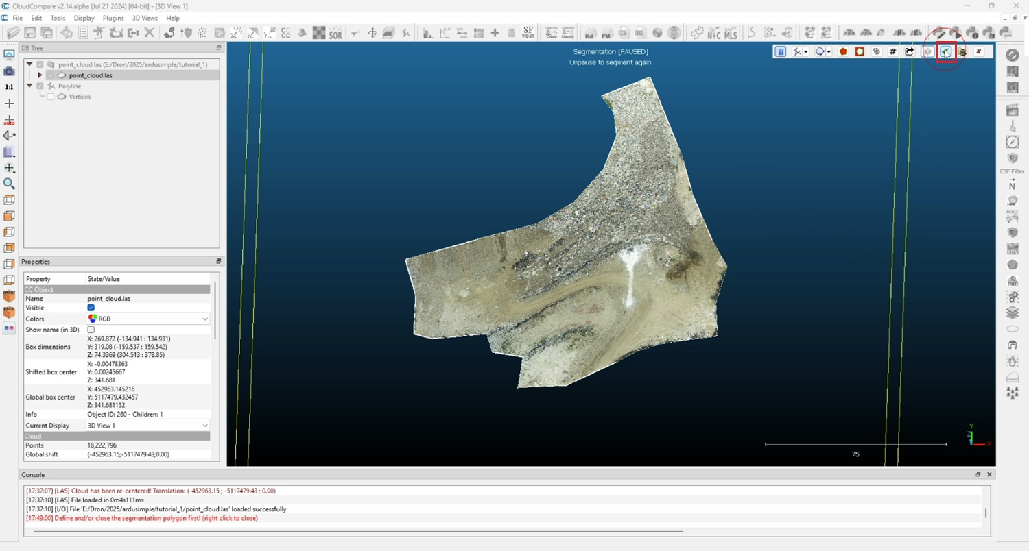
  1. Zoom the model and click the Polyline editor icon.
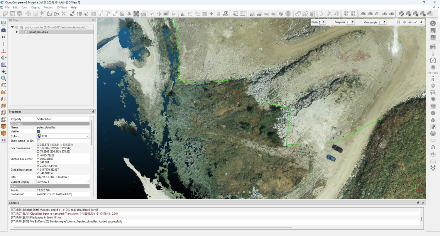
  1. Left-click in the view window to place the first vertex. Continue left-clicking to outline your boundary. Right-click to finish the sketch.
  1. Click the Segment tool (scissors icon).
  1. Choose Use Existing polyline.
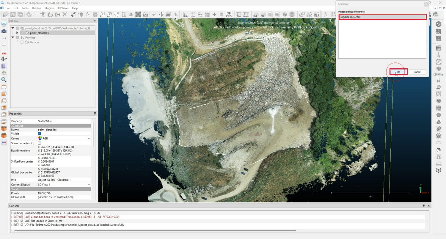
  1. Select your polyline and press OK.
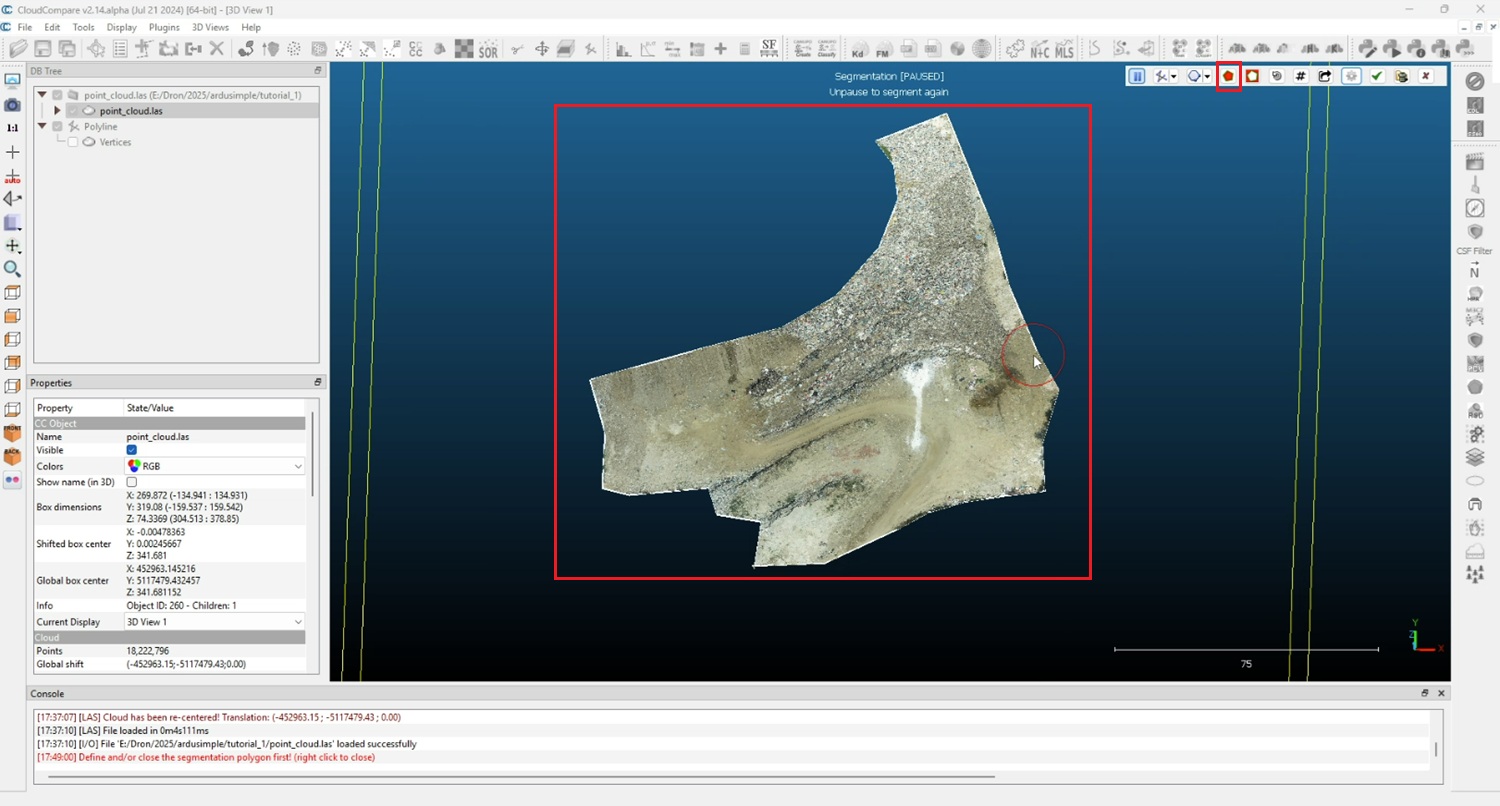
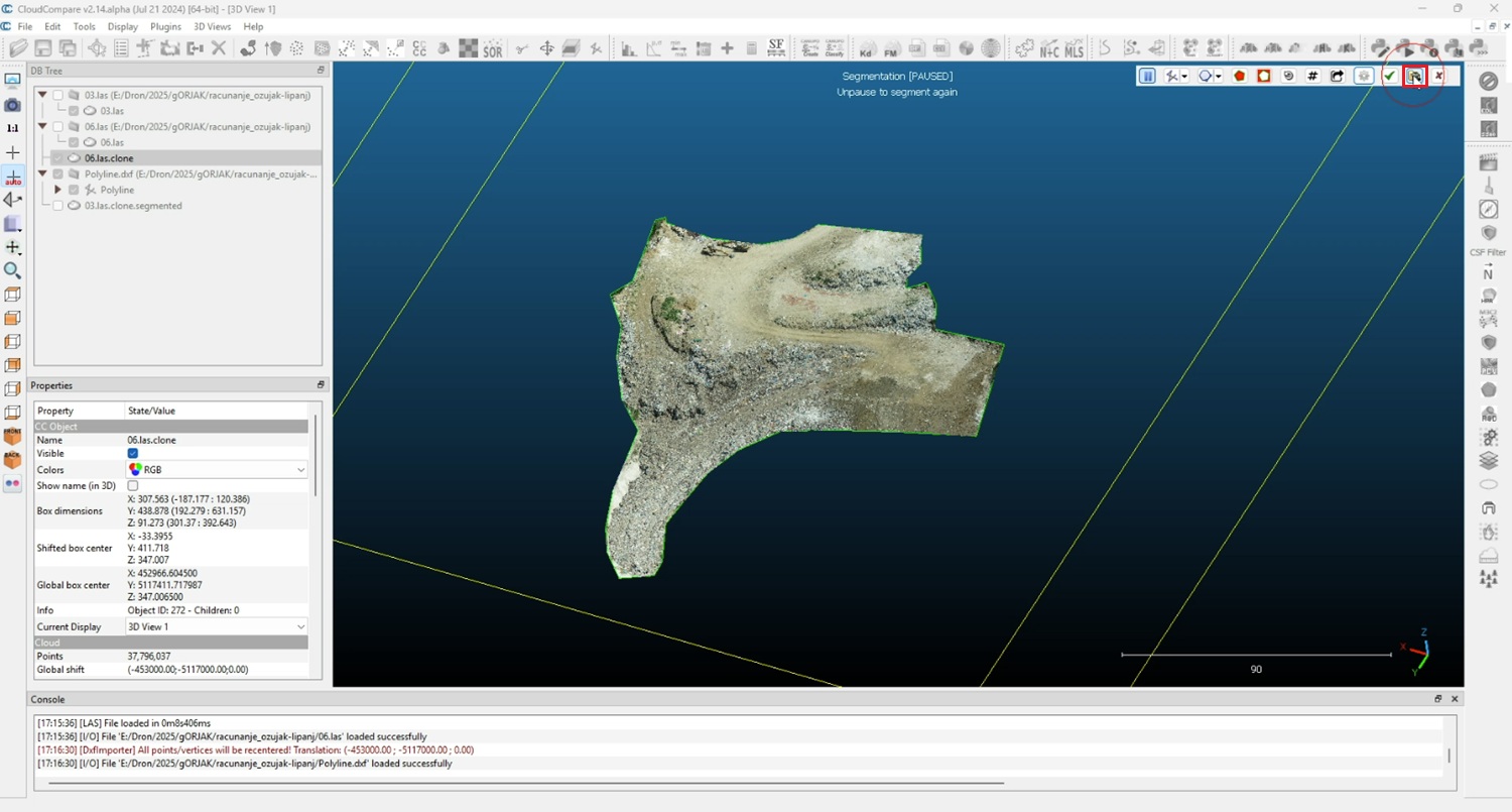
  1. Click Keep points inside (polygon icon). The segmented area will appear.
  1. Click Confirm segmentation.
  1. Press Delete segmented points.
  1. Open second model by following the steps #46-#49.
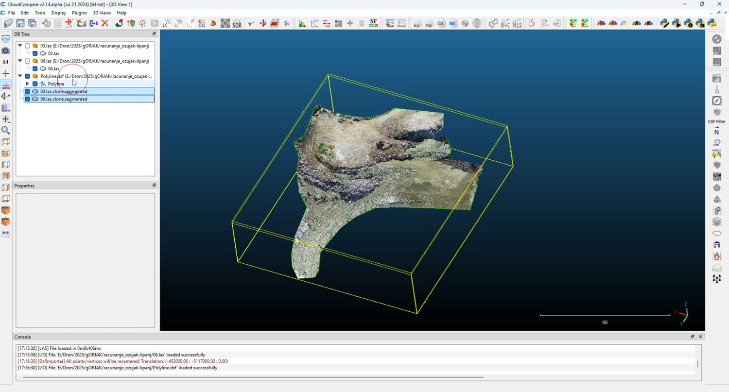
  2. Create segment for the second model by following steps #52-#57.
  3. Click on your polyline on DB Tree window. Click File->Save. Choose DXF  in the format list, type the filename (e.g., Polyline.dxf) and click Save.
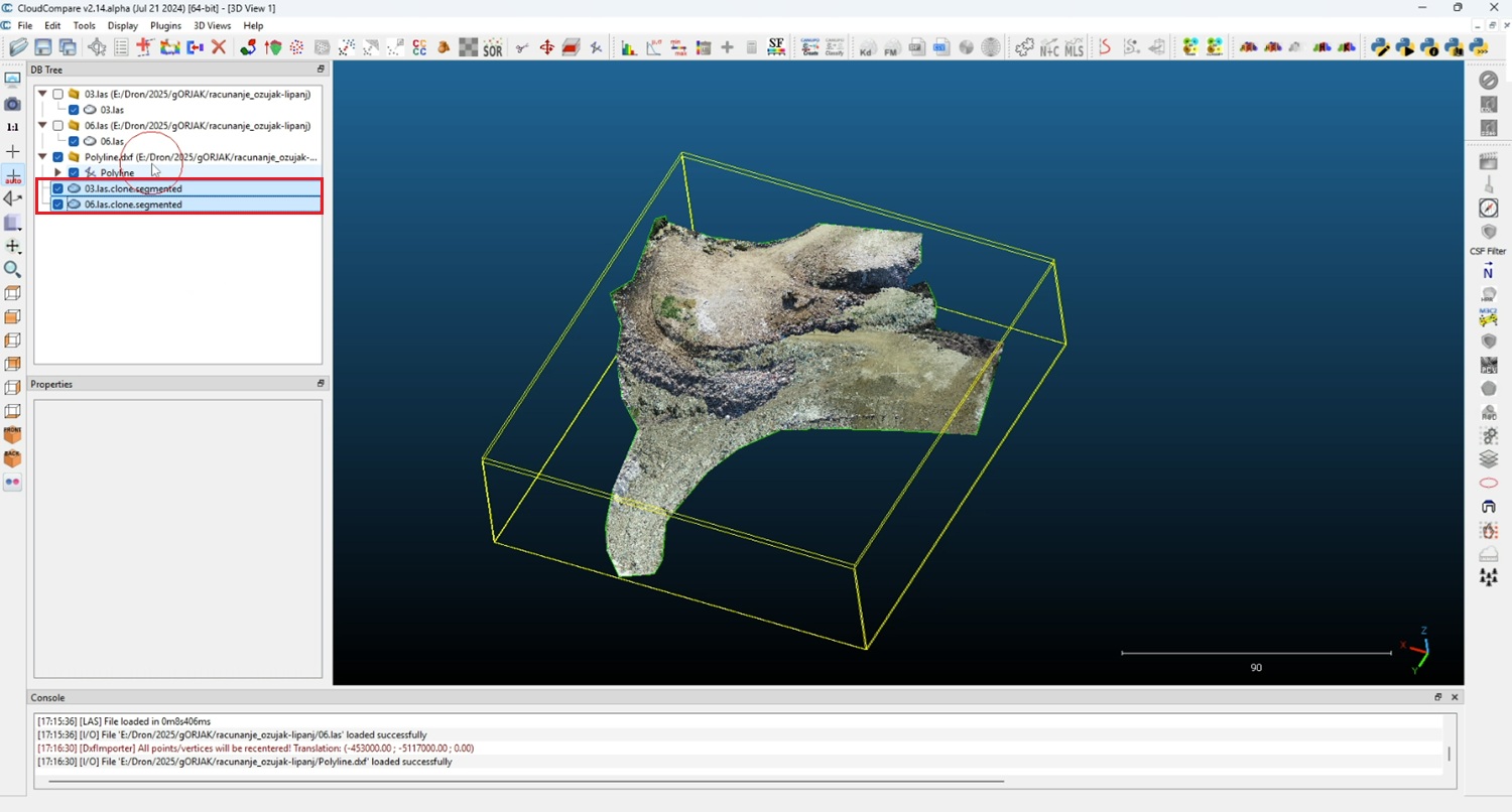
  4. Once finished you will have two surveyed segment ready for volume calculation.

Volume calculation

  1. Ctrl+click to select both segmented models in the DB Tree.
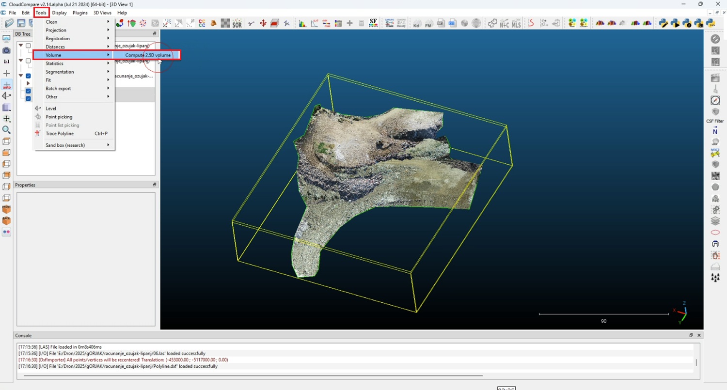
  1. Go to Tools->Volume->Compute 2.5D volume.
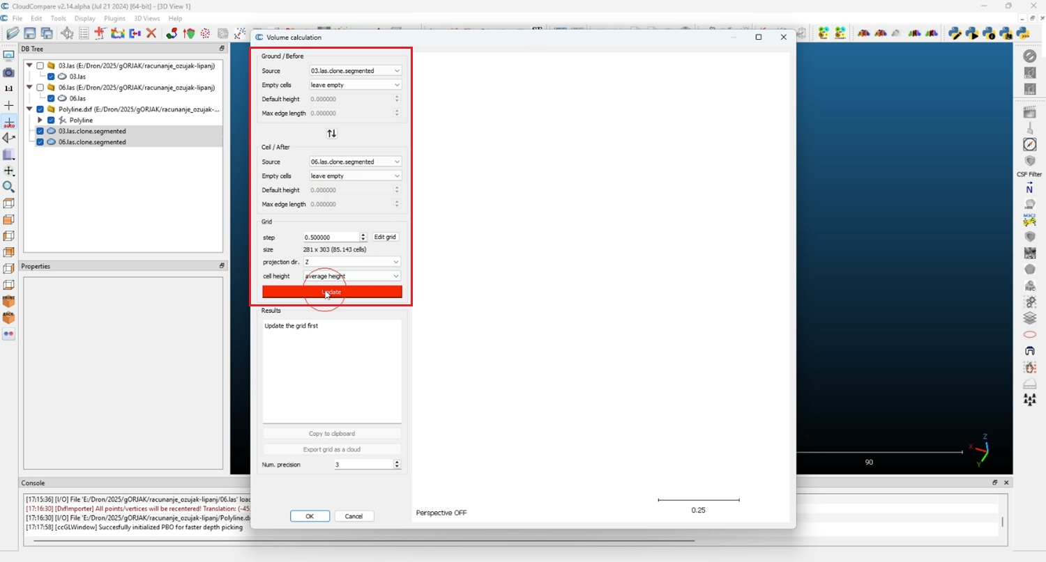
  1. In the dialog, set Vertical direction = Z, set Grid step, select Ground (reference) = Before and Ceil (compared) = After, then click Update to preview.
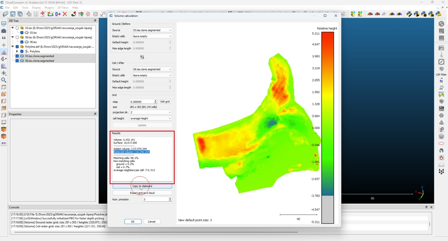
  1. The dialog will display Added volume, Removed volume, and Net volume. You can use this data to check the contactor’s quotation.

If you want to follow this tutorial, we have all the products in stock and ready to be shipped:

If you liked this content, you can follow us on Twitter, YouTube, Facebook or LinkedIn to stay updated of content like this.

Got any questions or requests?
Contact us! We'll answer <24 hours!

Icon
Contact ArduSimple
Close

Want to learn more about GPS/RTK?

1. Our engineering team will contact you to solve any questions
2. We will keep you updated about promotions and new product releases
3.You will only hear from us when we have important news, we won’t spam your email