simpleRTK2B+heading hookup guide

Hardware overview:

You can use simpleRTK2B+heading as a standalone board or as an arduino / Raspberry Pi shield.

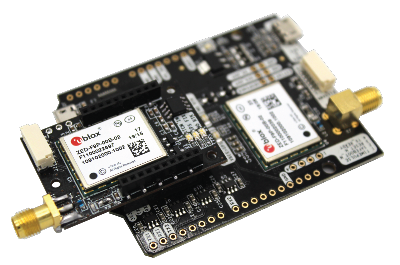
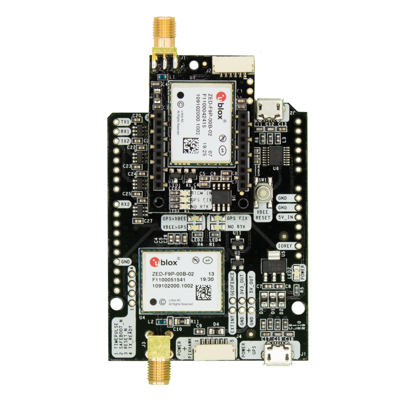
The main components of simpleRTK2B+heading are:

  • simpleRTK2B (using ZED-F9P, used as “heading” board)
  • simpleRTK2Blite (using ZED-F9P, used as moving base and optionally rover from a fixed base station at the same time)

If you are an advanced u-blox GPS user, you might want to have a look at the very extensive u-blox documentation.

Used standalone, simpleRTK2B+heading will provide you with very accurate RTK heading (0.4deg @ 50% with 1 meter distance between antennas), and standard dual band position accuracy (1.5m CEP)

You can upgrade your simpleRTK2B+heading board to also provide you with RTK position accuracy, by connecting it to an NTRIP server or adding one of our base station options:

Power:

The simpleRTK2B+heading board can be powered from 4 different sources:

  • GPS USB port
  • XBEE USB port
  • Pixhawk connector
  • Arduino rail

Only 1 of them is needed to use the board, but you can also connect the 4 at the same time, there’s no risk.

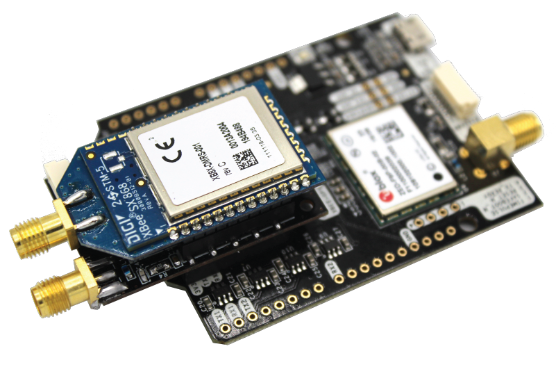
Communication ports:

simpleRTK2B+heading has a few interfaces that we will now explain in detail

USB connectors

Each USB will provide you with different information:

  • POWER+GPS: Will let you communicate with the simpleRTK2B Budget board native USB port. Will provide you heading information with message UBX-NAV-RELPOSNED. Heading is not available in NMEA format (limitation from ZED-F9P). In addition, it will also actually provide you the relative vector (North East Down) between the 2 antennas.
  • POWER+XBEE: Will let you communicate with the simpleRTK2B Lite board via its UART1. Note that by default position data output is disabled and only RTCM data output is enabled. If you want to see readable data from this port, you can enable NMEA or UBX messages from u-center, with the correct baudrate (enable autobauding), View > Messages View > right click “enable message”.

Arduino rails

Alternatively arduino rails can be used to interface with an external processor / arduino:

  • GND: ground is available in the standard arduino pins. You should always connect this line to your other board.
  • 5V_IN: you can power simpleRTK2B from this pin, compatible with the rest of arduino boards.
  • IOREF: this is an input that will define the voltage levels of the next pins. If you input 1.8V, the next pins will be 1.8V level. It supports from 1.2V to 5.5V.
    • TX1: simpleRTK2B ZED-F9P UART1 TX (you will receive UBX-NAV-RELPOSNED in this pin)
    • RX1: simpleRTK2B ZED-F9P UART1 RX
    • TX2: simpleRTK2Blite ZED-F9P UART1 TX (you will receive NMEA or UBX position in this pin)
    • RX2: simpleRTK2Blite ZED-F9P UART1 RX.

Pixhawk connectors

2 available standard JST GH that can be used to connect the simpleRTK2B+heading to a Pixhawk autopilot.


The Pixhawk JST-GH connector is following the Pixhawk standard:

  • 1: 5V_IN
  • 2: RX (3.3V level)
  • 3: TX (3.3V level)
  • 4,5: Not connected
  • 6: GND
The 2 connectors will provide you with different information:
  • simpleRTK2B Pixhawk connector: Will provide you heading information with message UBX-NAV-RELPOSNED. Heading is not available in NMEA format (limitation from ZED-F9P).
  • simpleRTK2Blite Pixhawk connector: Will provide you with absolute position in NMEA or UBX format.

Antennas

GPS/GNSS Antenna

simpleRTK2B+heading requires 2 good quality GPS/GNSS dual band antenna. The board is compatible with both active antennas supporting 3.3V supply and passive antennas. The maximum output current is 75mA @ 3.3V.
If you use it with the traditional cheap GPS antennas widely available, you will not achieve the expected performance.
That being said, just connect the antenna to the SMA connector without using tools (the strength of your fingers is enough).
It is recommended to connect the antenna before powering the board.

The installation of the antennas is also a key point to achieve the best results.
The GPS/GNSS antenna should always be installed with the maximum possible view of the sky.
In addition, if possible, it should be installed with a metallic plane behind, e.g. rooftop of the car, on a metal plate bigger than 20cm, etc.

The minimum recommended distance between both antennas is 1 meter. The larger the distance, the better the heading accuracy.

If you want to learn how installation impacts performance, please have a look at our GPS/GNSS antenna installation guide.

Want to learn more about GPS/RTK?

1. Our engineering team will contact you to solve any questions
2. We will keep you updated about promotions and new product releases
3.You will only hear from us when we have important news, we won’t spam your email