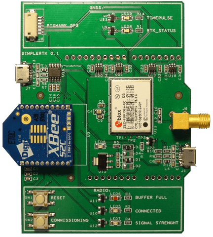
Product update simpleRTK2B: first ZED-F9P application board + future specs


The wait has been long but we finally have them in our lab …
… give a warm welcome to the first application board using ZED-F9P!
So far we have tested the same PCB with a regular NEO-M8P GNSS module.
This has been great for generic tests but when it comes to performance, it didn’t make sense to invest a lot of time since the core of our simpleRTK2B application board was still not there.
Well, now we can. We couldn’t wait to start the planned test campaign and we jumped to the field to see if the hype was worth it.
In the next post we will show these preliminary results.
As we said in the previous post, we removed the flying wires and now our prototype looks much better, but it’s still a prototype.
We have done some tests during the past weeks and for the final version we plan to introduce the following changes:
- The size and the weight of the PCB doesn’t make us happy, we will reduce both so it fits the Arduino UNO form factor (69x53mm)
- Using two USB connectors (radio + GNSS) may be confusing so we will use only one USB connector that will talk by default with the ZED-F9P
- We will add a switch to allow radio configuration via USB, which is something you won’t play with on a daily basis but it’s still needed for some advanced projects
- During the tests we had to look continuously to the schematics to find the function of the header pins.
We don’t want you to do the same so we will print labels on all the used pins in the PCB. - Another struggle we had to deal with was to remember which board was the base and which one was the rover.
We handled that one easily by sticking some paper on each board.
In the next version we will print a white area in the PCB so you can write base/rover/… and will be easy to clean up in case you change your board functionality - On the first prototype we placed many LEDs and buttons to get as much information as possible.
At the end we only looked at a few of them and the rest were only confusing us. The next design will reduce the number.
If you are missing some of them don’t worry, we will place some pads on the PCB so you can easily add the removed functionality
 and
and 


